MSR / MSCB Photos: Interior
Transmitter
- Photo Sources:
- 0nnn: Anonymous WECo engineer
-
1nnn: Ves Fulp -
8nnn: ABM Research and Development at Bell Labs -
9nnn: Don Felten -
Annn: Pam Bodenheimer Hiltner -
Innn: Clint Esckilsen via Facebook (3) -
Vnnn: SRMSC Tactical Area Virtual Tour (link on home page) <$
- Photo Descriptions:
- Ves Fulp
-
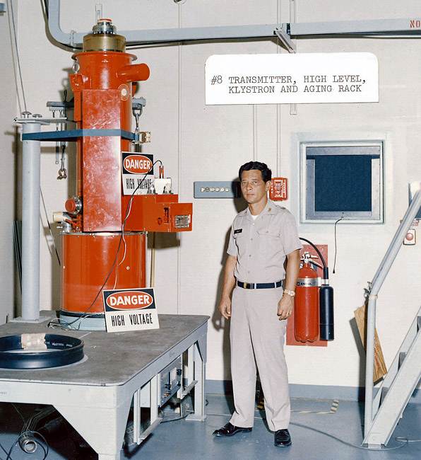
ABM Research and Development at Bell Labs
- The MSR transmitter was so massive physically and technically that it can't be described easily in a few words. These descriptions are extracts from a final document I was asked to write after the MSR site deactivation. It was used by some government organization (I believe it was GSA) to send out to other military, government, and civil organizations to see if any of them wanted any of the equipment. I want to point out that although I wrote these overviews for use by GSA, I used existing documents and publications created by Raytheon, Bell Telephone Labs and Western Electric.
- Overview
- Detail
- Other miscellaneous transmitter recollections:
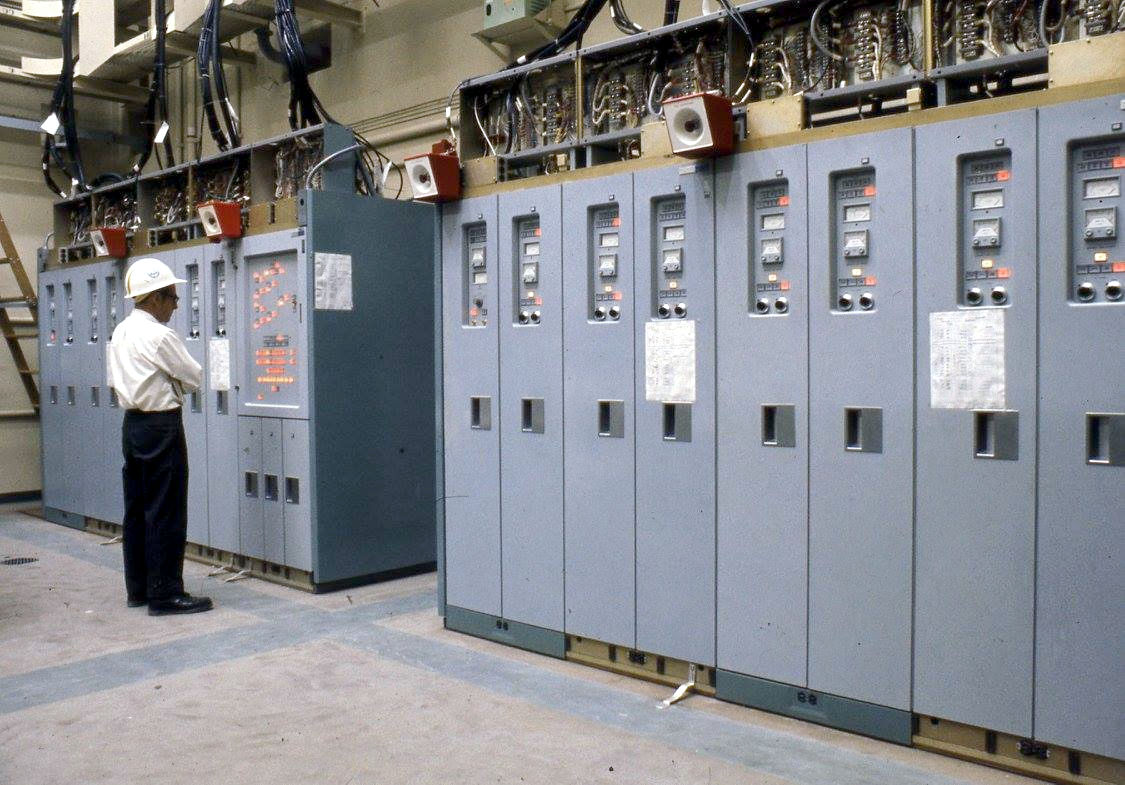
High Voltage Room
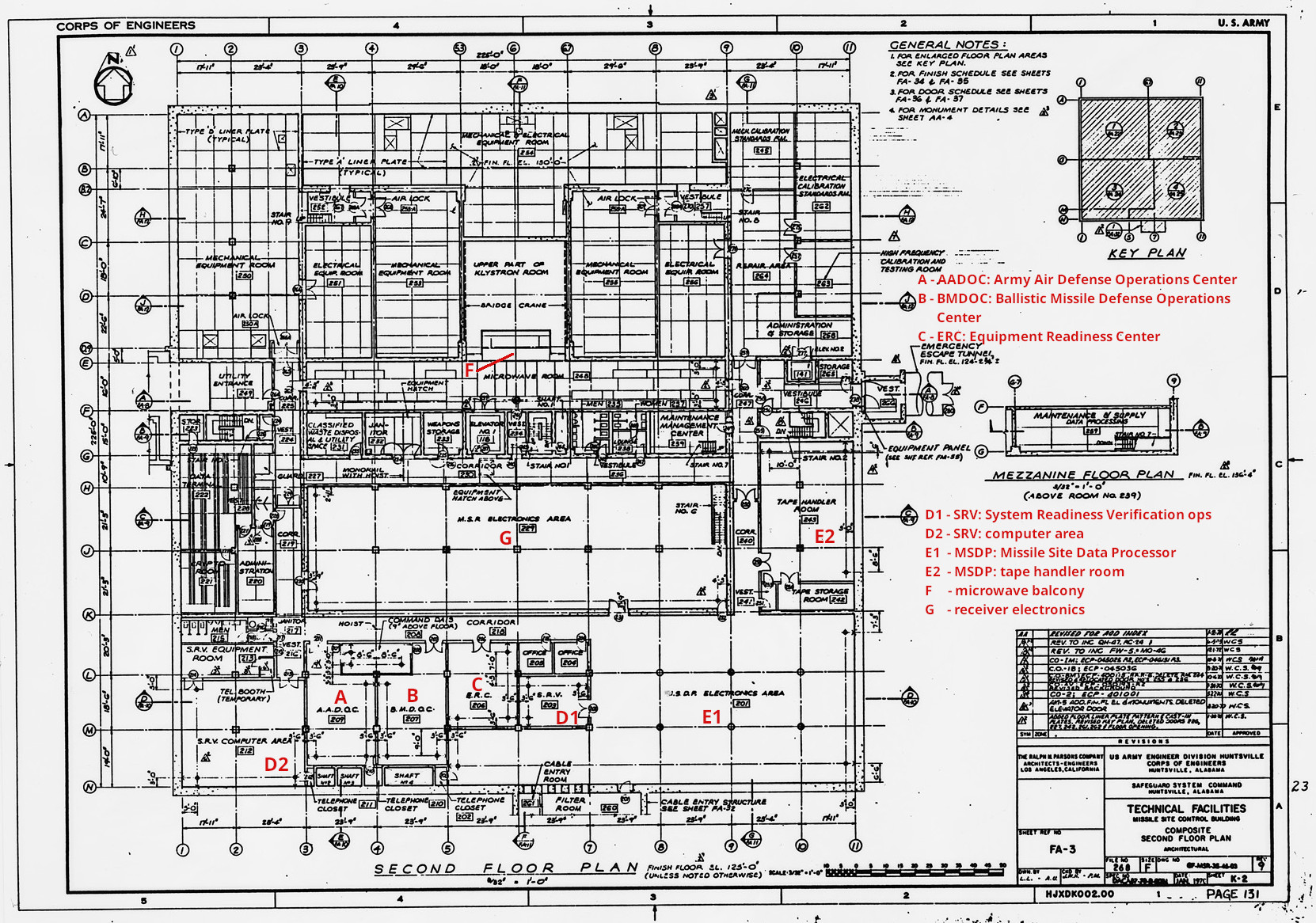
- Rooms 132, 136; Control Rooms 133, 137. <$
- As with most MSR components, there were two high voltage rooms for redundancy.
- Extensive safety precautions, including Kirk key systems, were employed to insure protection of personnel.
-
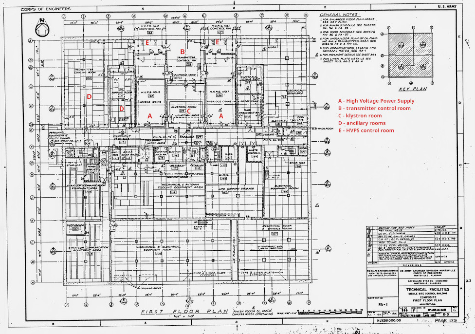
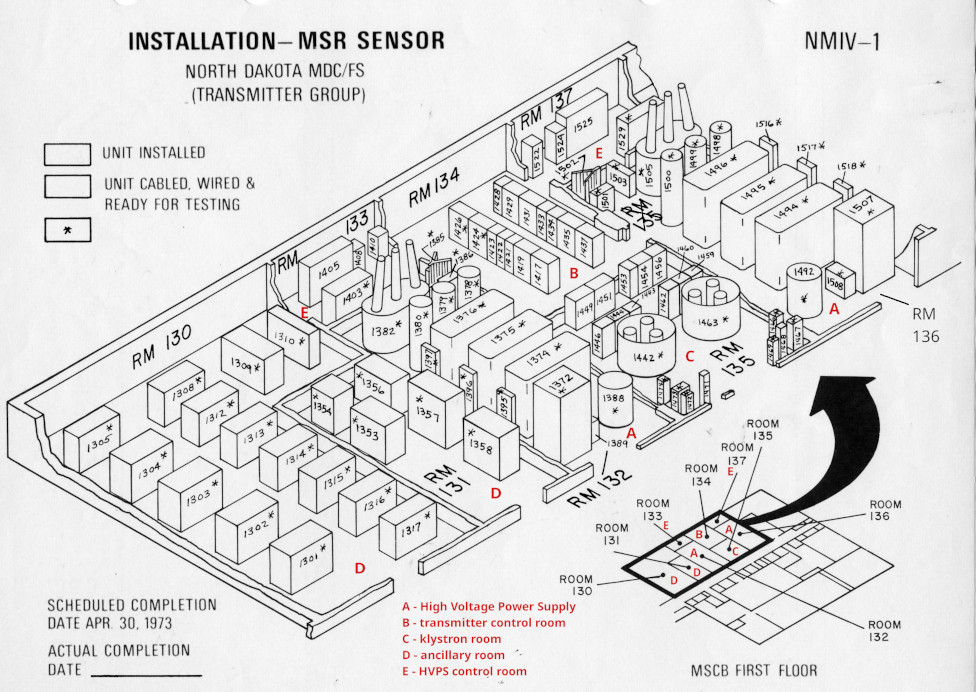
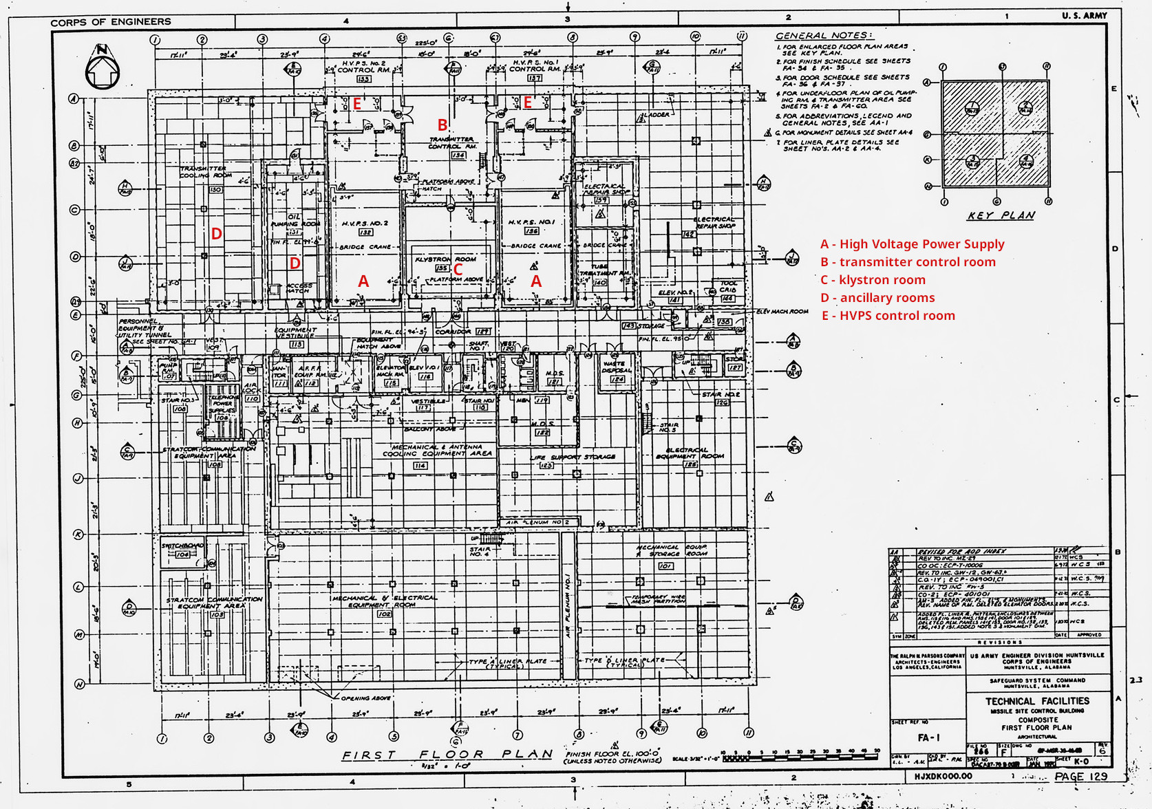
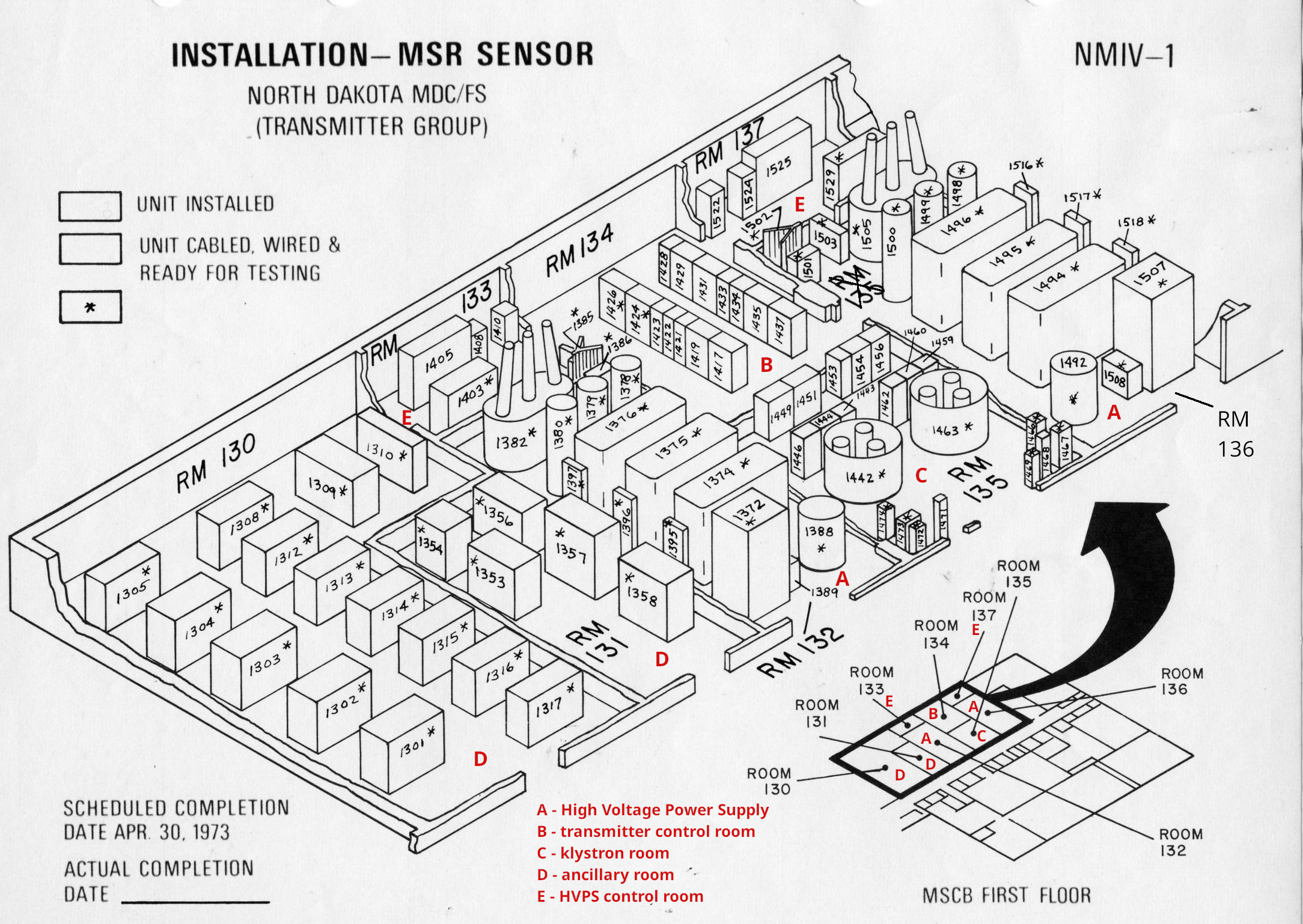
7356e, 1117e: <$
- A: High Voltage Power Supply (HVPS), Rooms 132, 136
- E: HVPS control room, Rooms 133, 137
-
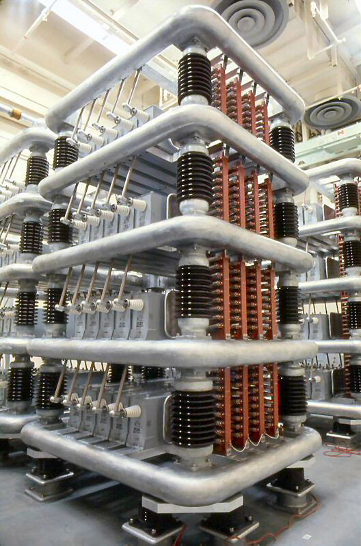
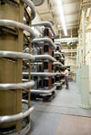
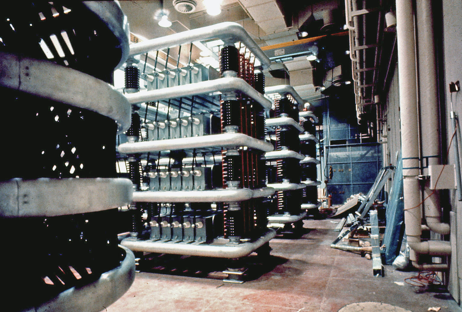
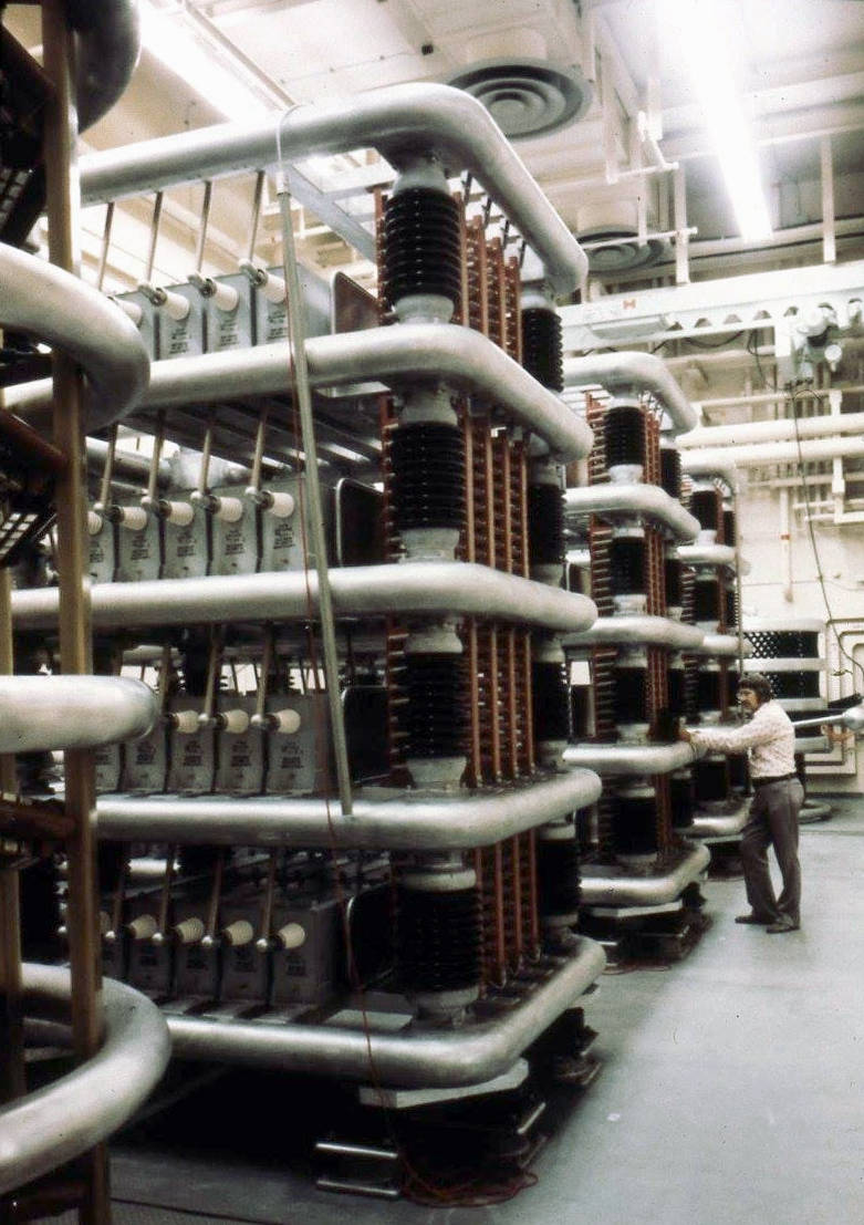
1066: Three capacitor banks with surge resistor partially visible at left (see 1048).
- There was a capacitor bank for each phase of the three phase power.
- The capacitor bank stored 250,000 coulombs of energy to supply power during the klystron beam pulse.
- 1065: Closer view of capacitor bank.
-
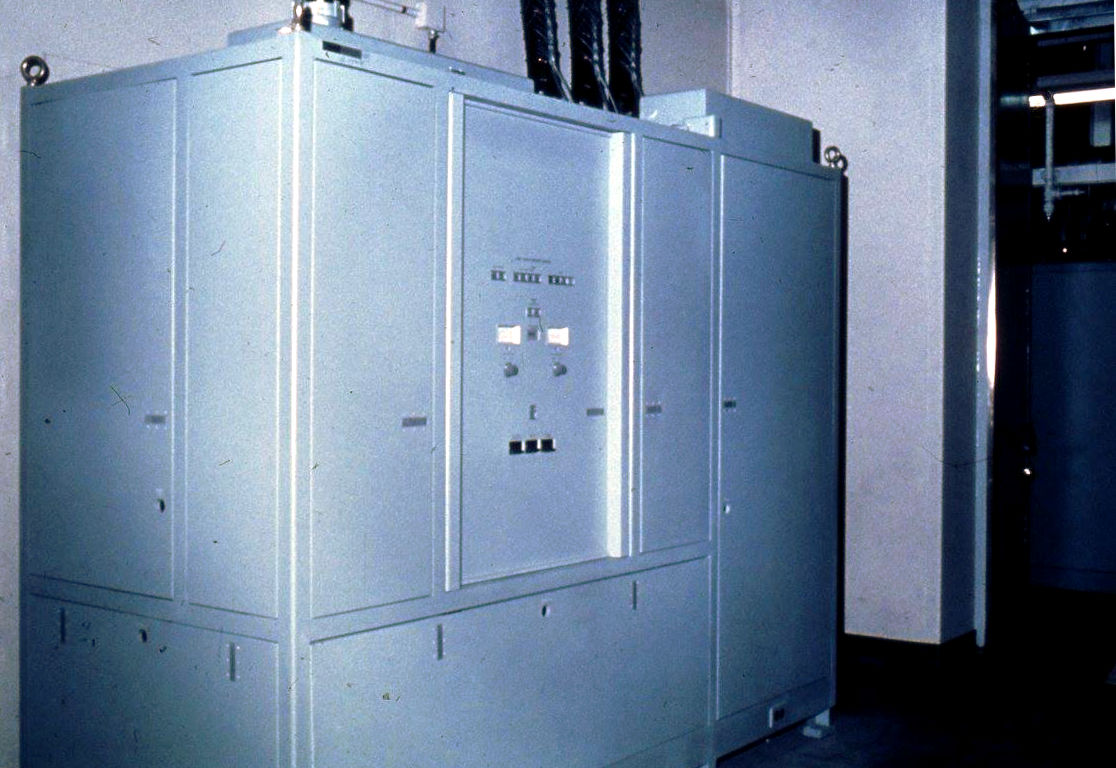
1064: Capacitor banks with rectifier stack partially visible on left (see 1076).
- Shock isolation equipment can be seen at right.
- Surge resistor can be seen in the distance at the end of the room (see 1048).
- Comments
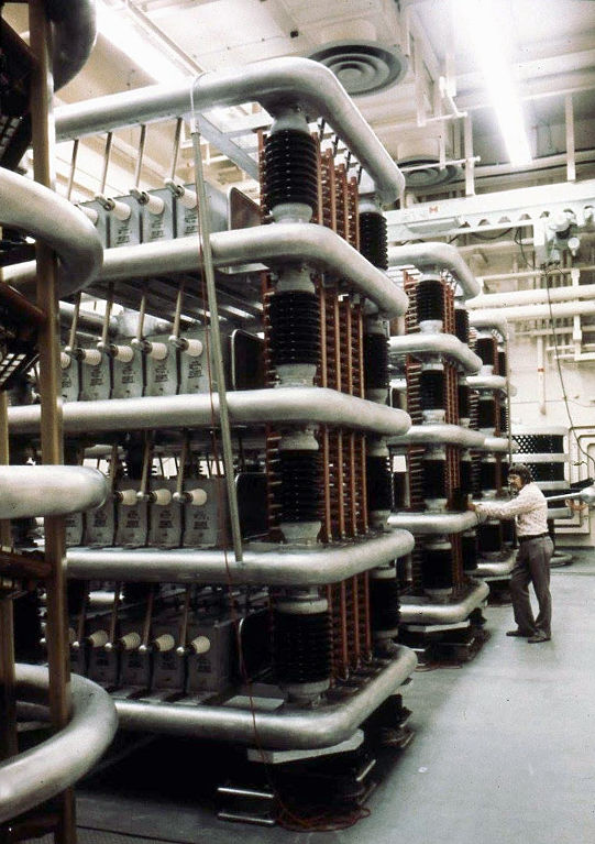
- I006: Capacitor banks.
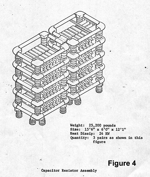
- 1098: Capacitor bank drawing with statistics.
-
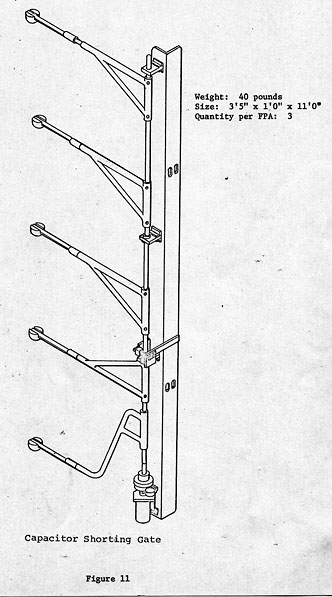
1099: Capacitor shorting gate.
- A shorting gate would contact each bank of capacitors to ground the residual charge when the door to the high voltage room was opened or there was some other requirement to dissipate the stored charge.
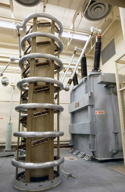

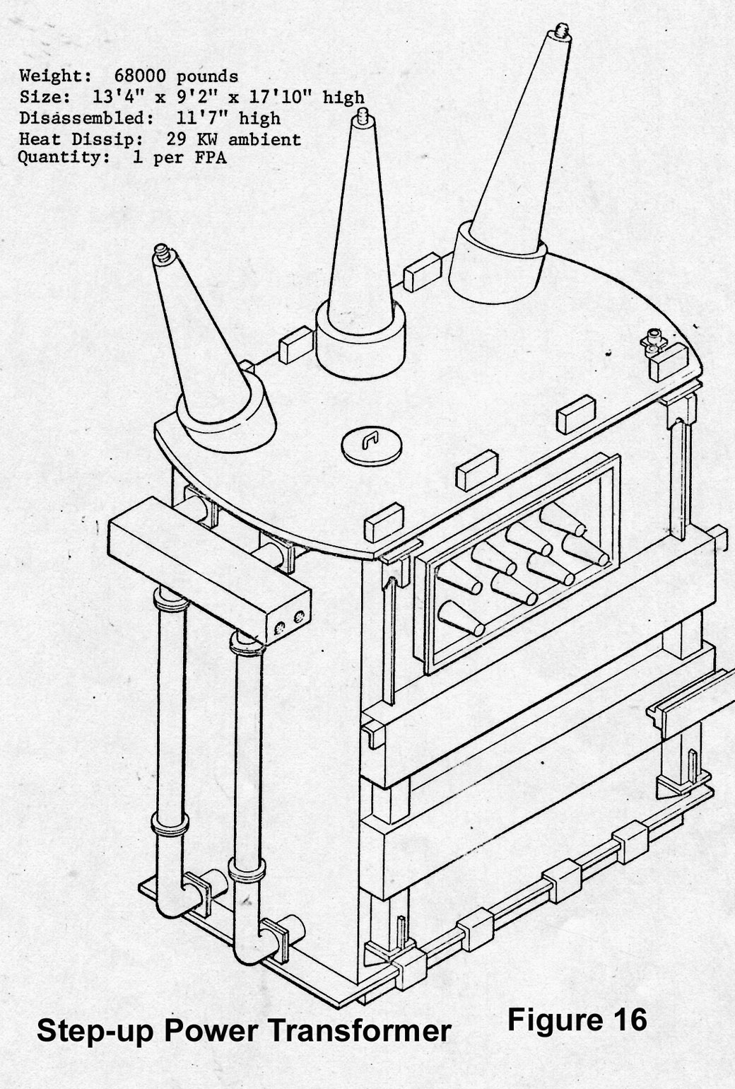
- 1076: Rectifier stack (left), step-up power transformer (right).
- I005: HVPS (High Voltage Power System) shorting bars.
- I017: HVPS (High Voltage Power System) control module.
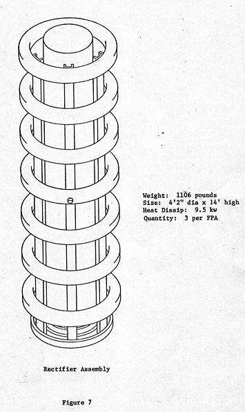
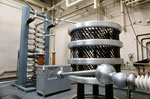
- 1107: Rectifier stack drawing with statistics.
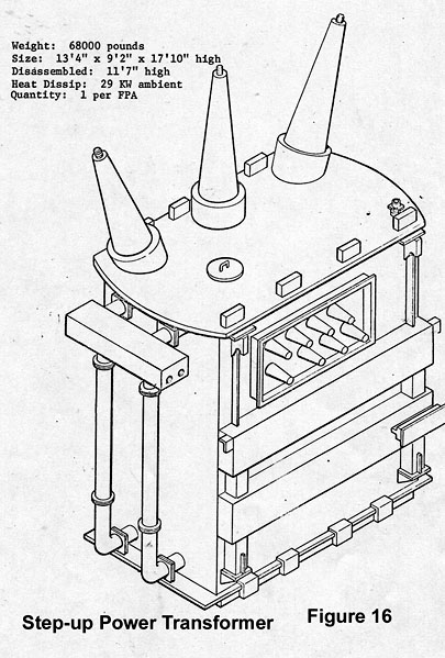
- 1110: Step-up transformer drawing with statistics.
-
1048: Crowbar (left), surge resistor (right).
- The crowbar's primary purpose was to protect the klystron from being destroyed by internal arcing or other malfunctions.
- Using a vacuum spark gap, the crowbar fired in case of TWT arcing, interlock operation, or other faults requiring rapid removal of high voltage.
- Comments
- I004: Crowbar closeup.
- 1103: Crowbar drawing with statistics.
-
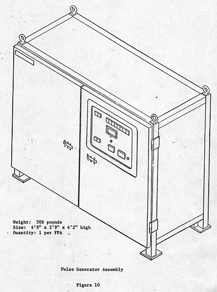
1105: Pulse generator assembly drawing with statistics.
- This small cabinet located directly in front of the crowbar generated the pulse necessary to fire the crowbar.
-
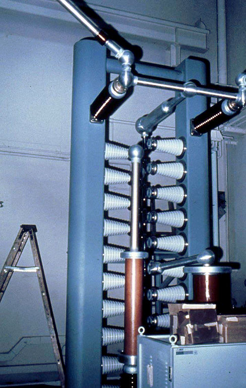
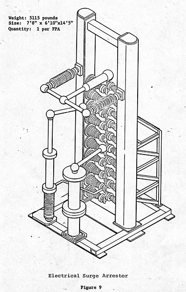
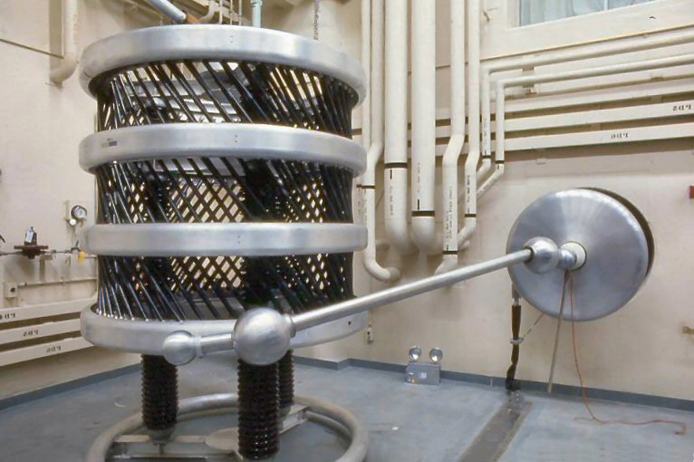
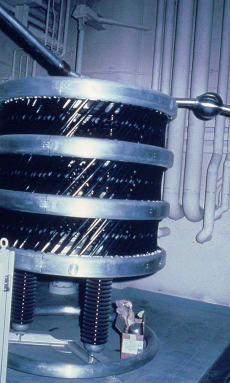
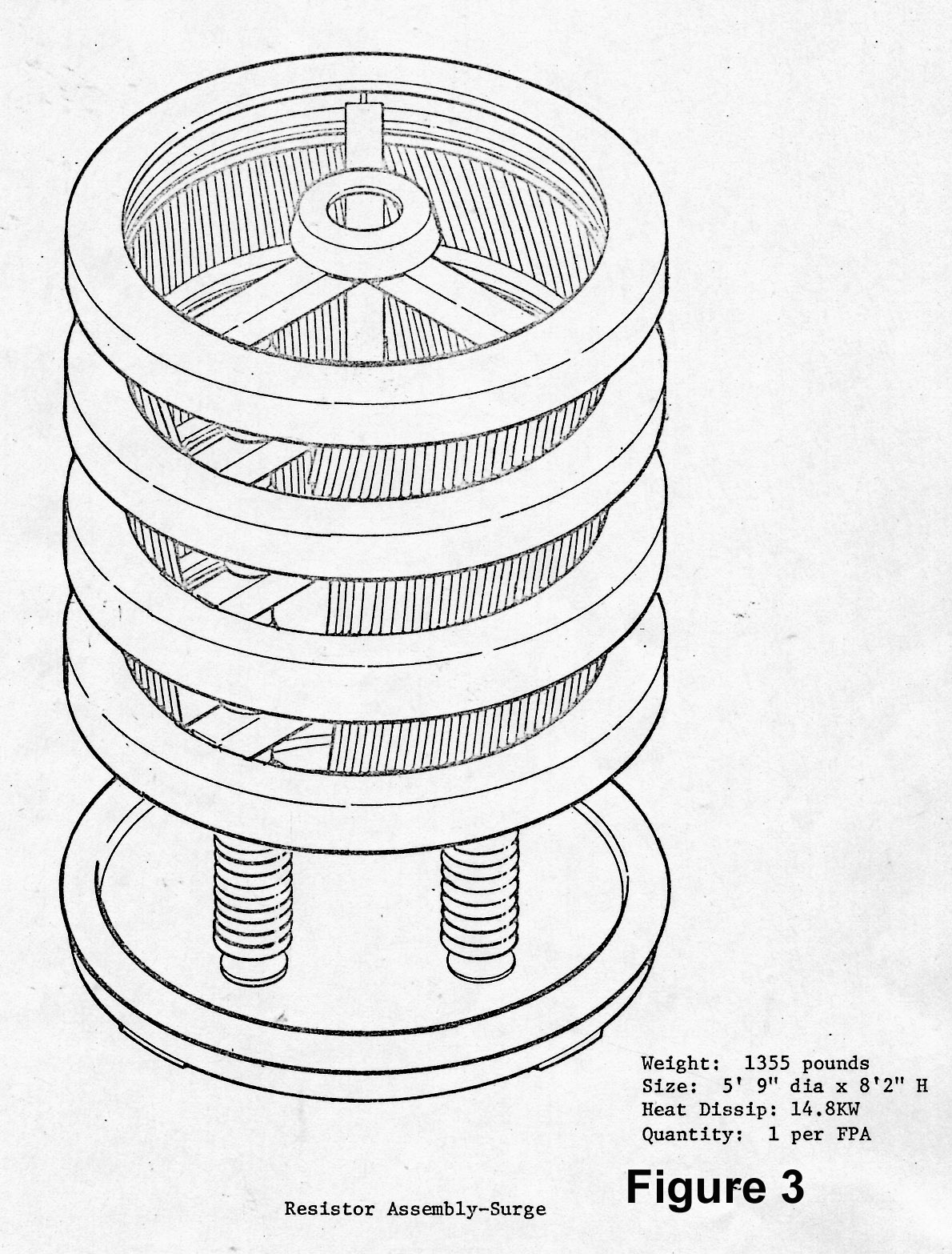
1077, I003: Surge resistor (or surge arrestor).
- 1077: The round plate on the wall is the "corona ring" where the high voltage comes in from the klystron room.
- Comments
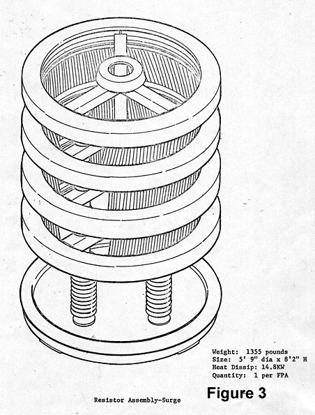
- 1108: Surge resistor drawing with statistics.

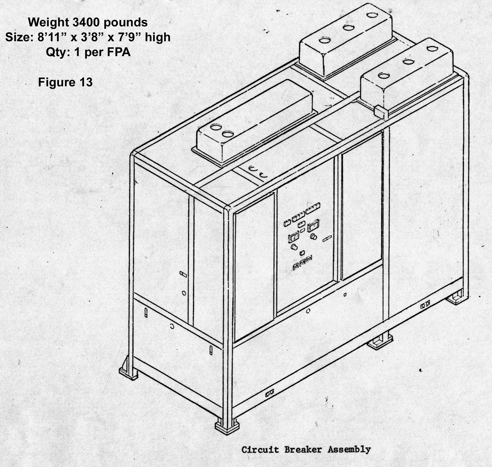
- 1100: Circuit breaker assembly drawing with statistics.
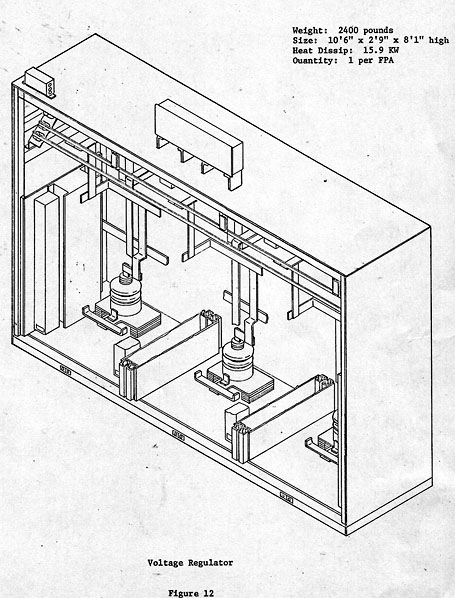
- 1111: Voltage regulator drawing with statistics.
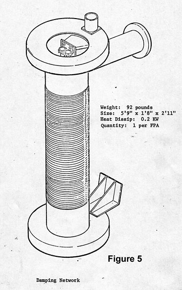
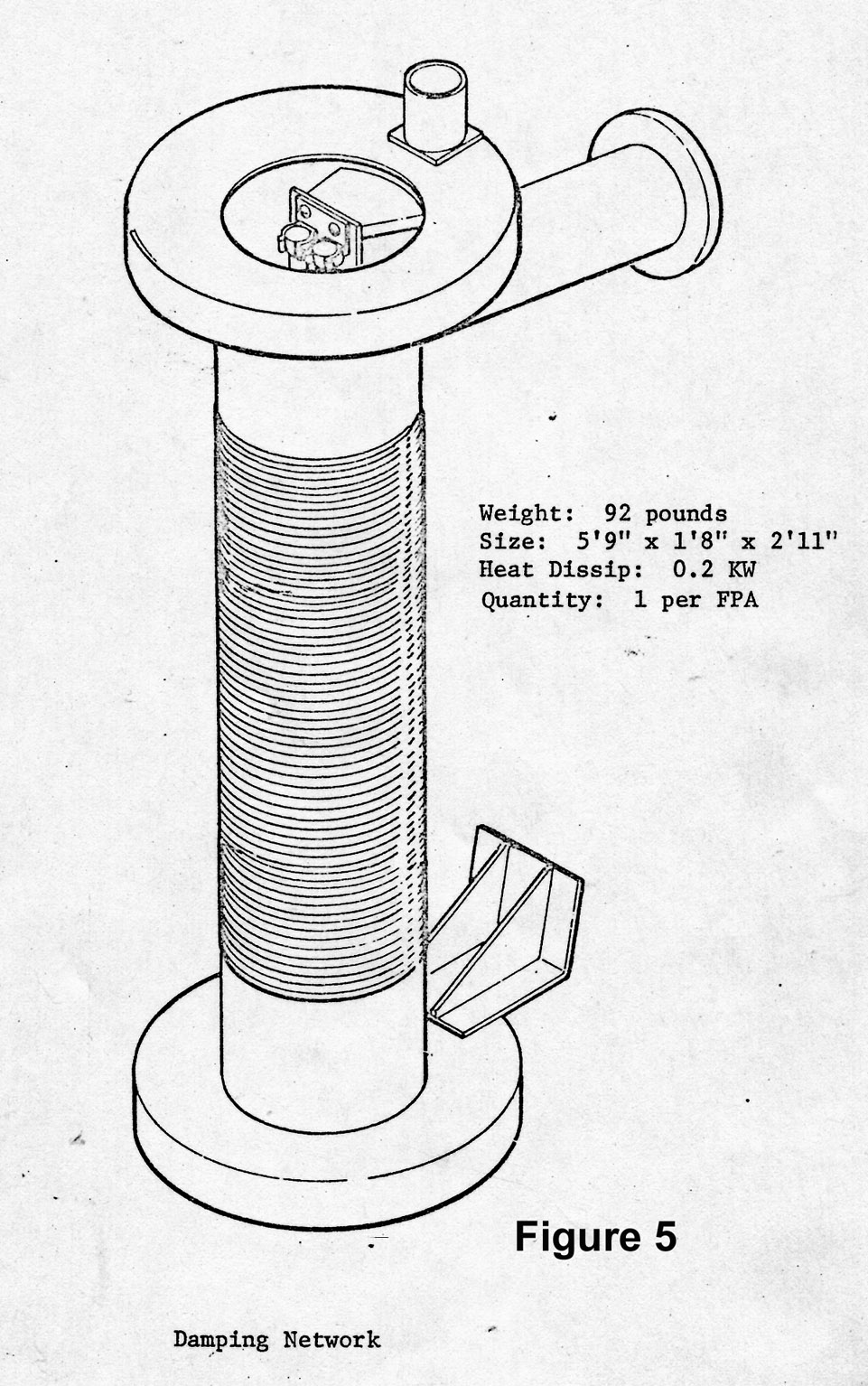
- 1101: Damping network drawing with statistics.
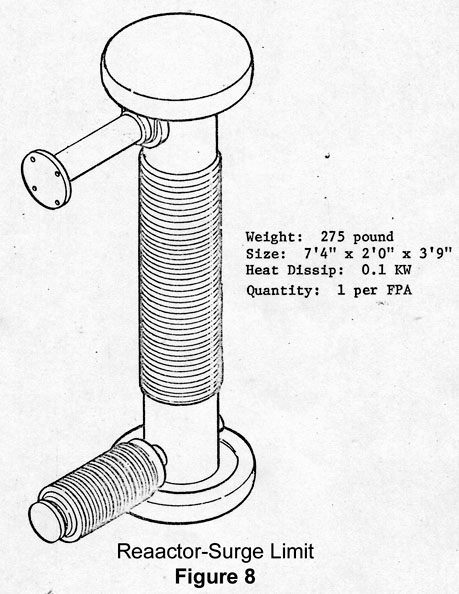
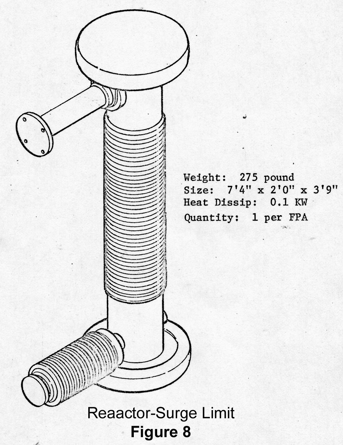
- 1106: Reactor-surge limiter drawing with statistics.
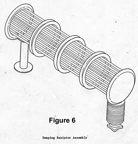
- 1102: Damping resistor assembly drawing.
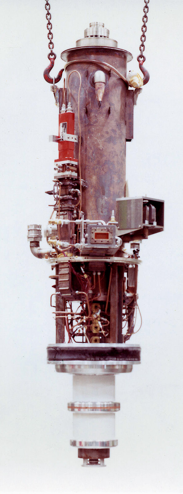
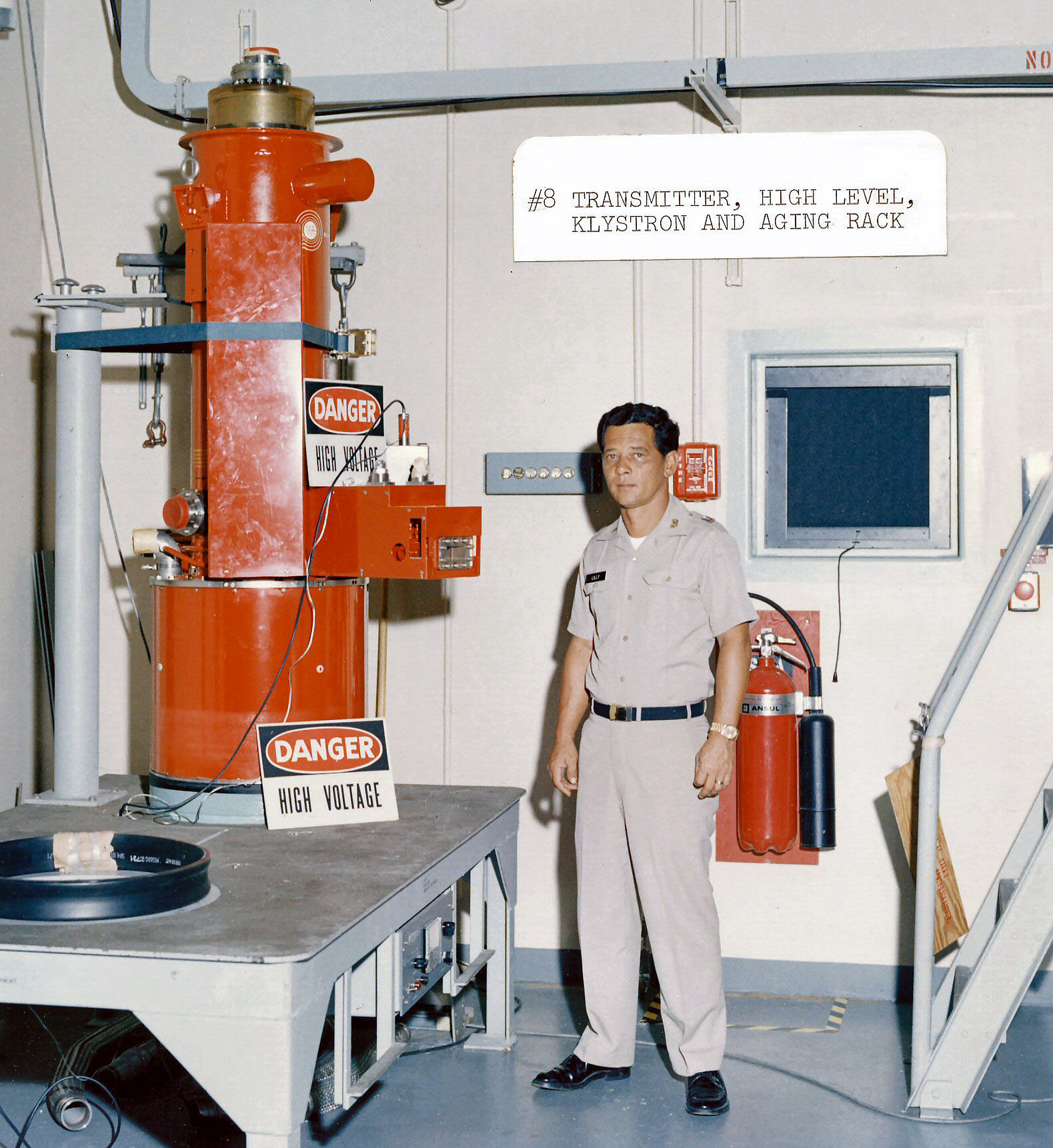
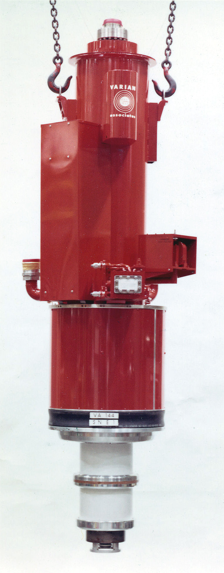
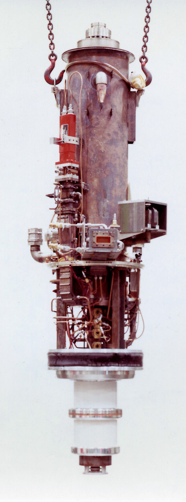
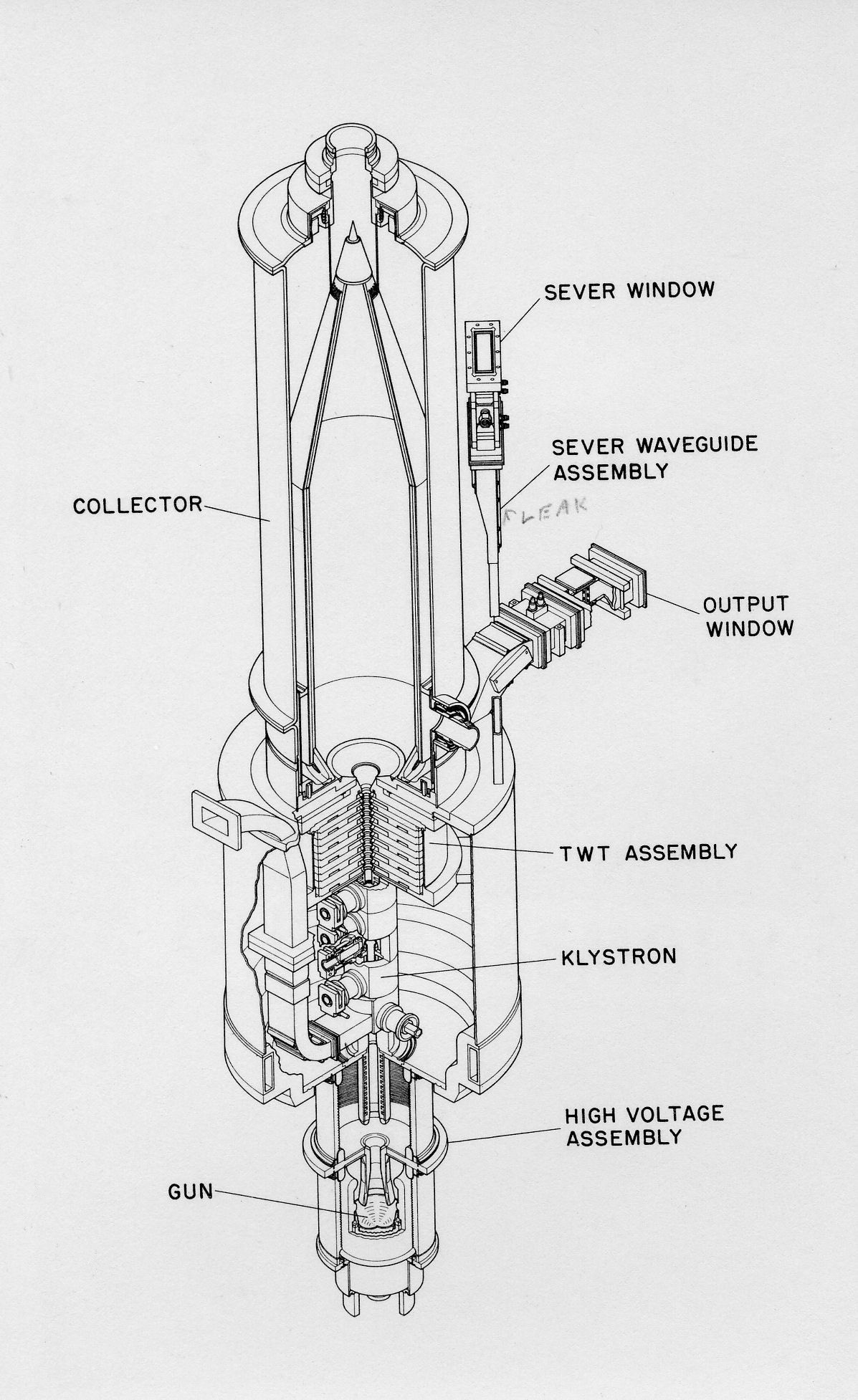
- The VA-144A high power klystrons used for the MSR were specially designed by Varian Associates. Due to the hybrid design incorporating a travelling wave tube (TWT), they were called twystrons.
- Al LaRue, one of the principal designers at Varian, was on-site in North Dakota during installation and testing of the tubes.
- Each of the two tubes cost approximately $750,000 (1970's dollars).
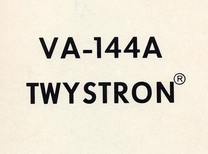

- 1092: Cover of a booklet describing the twystron.

- 1093: Outer cover removed.
- 1090: Component diagram.
- A001: Joe Gaye (Raytheon employee) working on the klystron - circa 1974.
- Room 135.
- Personnel were required to wear X-ray badges.
-
7356e, 1117e: <$
- C: Klystron room, Room 135
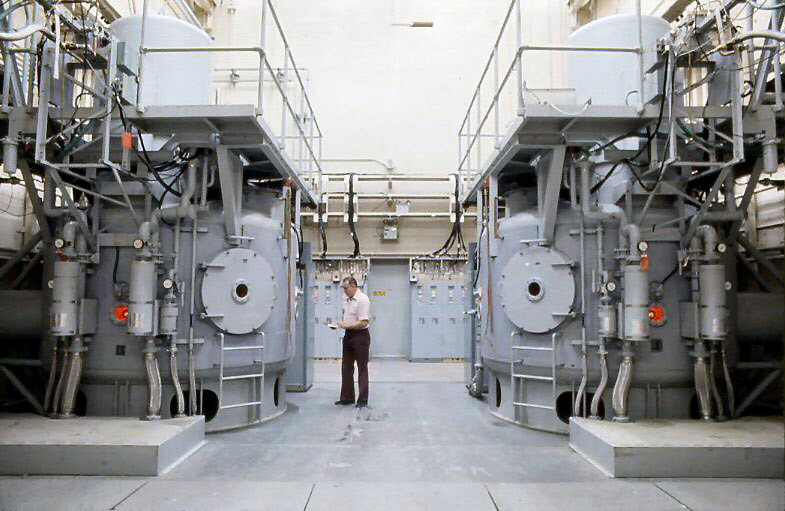
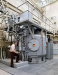
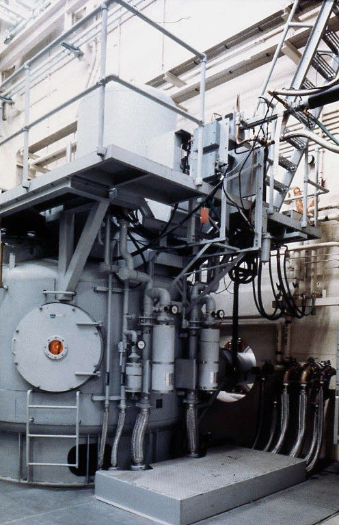
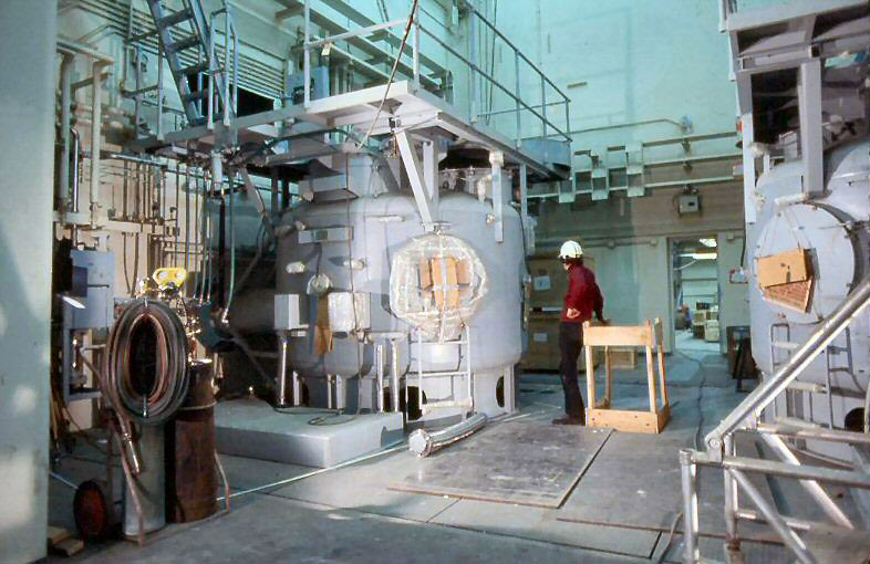
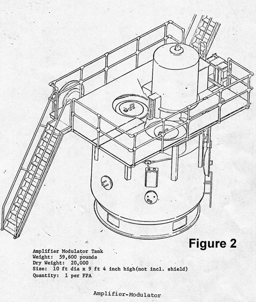
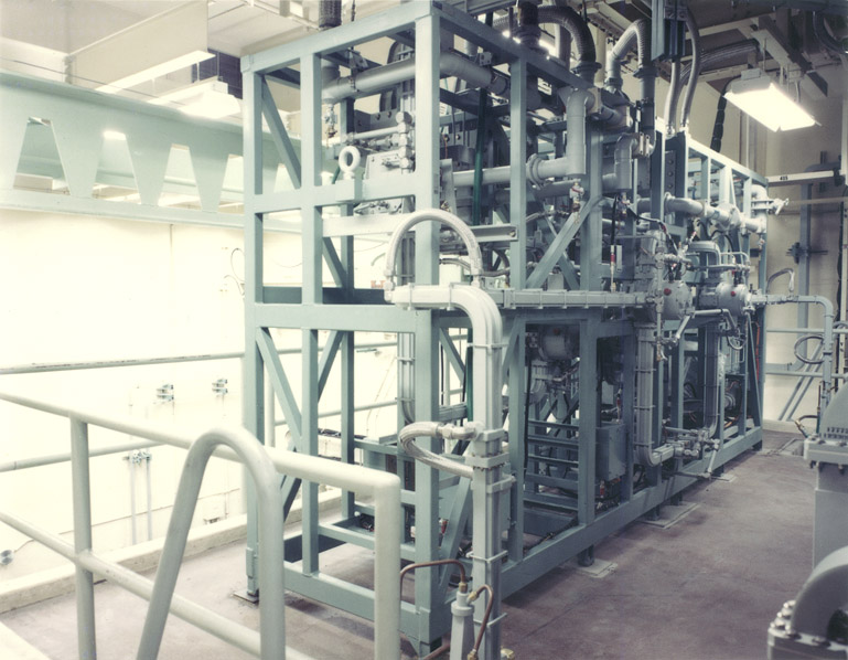
- 1069: Each of the two klystrons is mounted in a tank containing 3,500 gallons of high dielectric strength transformer oil. Comments
-
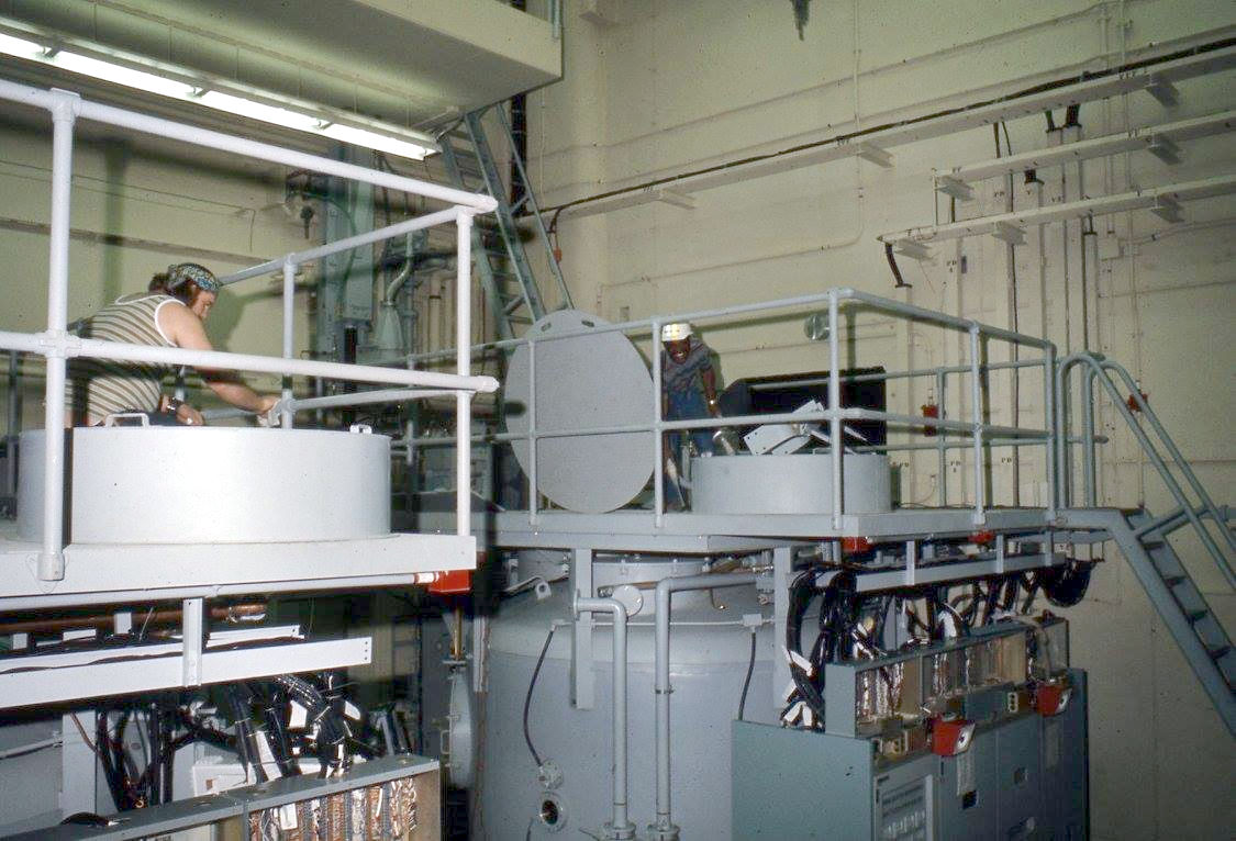
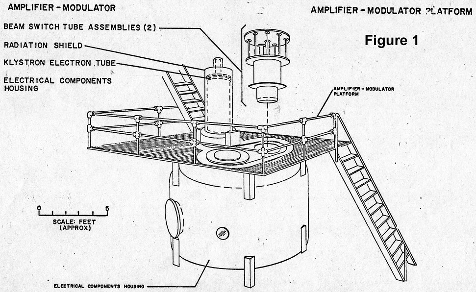
1070, 1074: Platform can be seen above each klystron tank.
- All components needed to pulse the modulating anode were immersed in the oil tank.
-
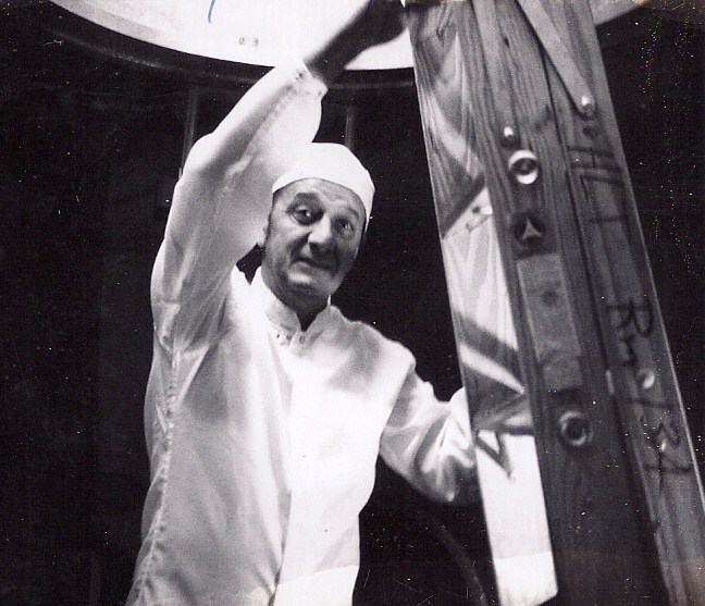
The water cooled collector portion of the klystron was housed under the shield on the platform above the tank. This shield was commonly referred to as the klystron "hat."
- Each shield weighed approximately 6,000 pounds was constructed of 3/4 inch lead with a 1/4 inch stainles steel liner to provide X-ray protection.
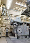
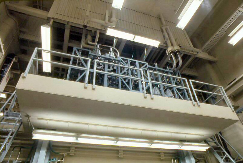
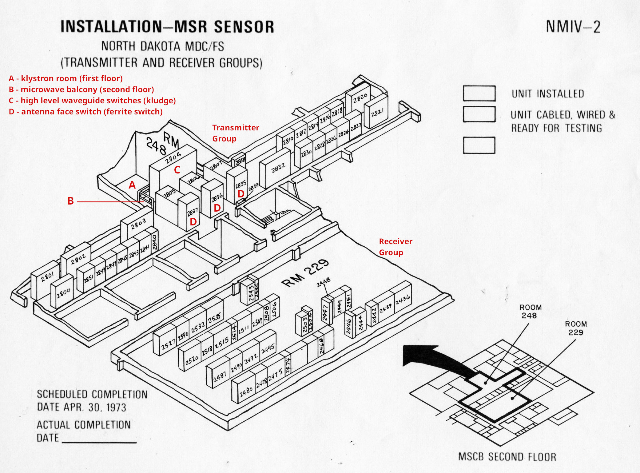
- 1074: The microwave balcony containing the high level wave guide switches (kludge) is in the upper left (above the fluorescent light).

- 1071: Closer view of the platform above one of the tanks and the klystron hat.
- 1037: Ves Fulp winds up one of the klystron hats. Comments
-
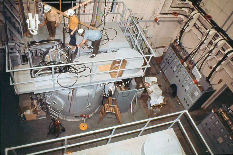
1072, I016, 1073: Tank installation.
- An overhead crane was used to lower the klystron tube through the opening and into its socket inside the tank.
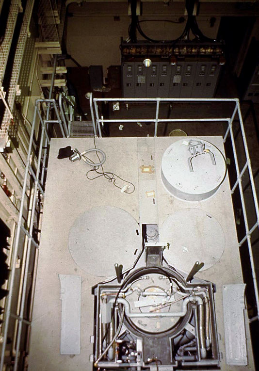
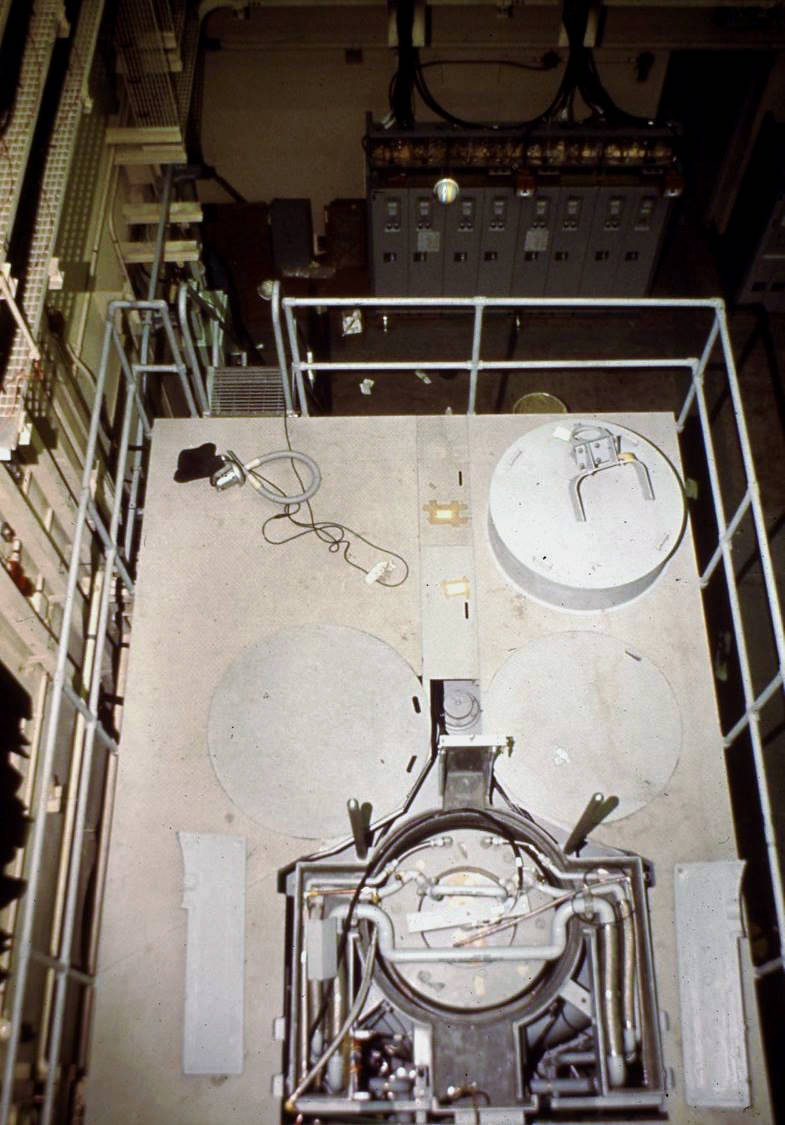
- I002: Overhead view of platform over klystron tank.
- 1096: Klystron tank drawing with components labelled.
- 1097: Klystron tank drawing with statistics.
- V029: Looking down into the klystron room from the microwave balcony in 2017. <$
-
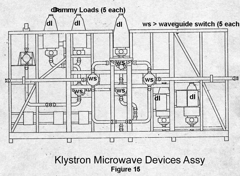
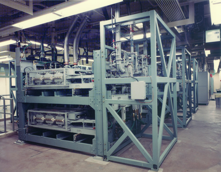
Controlled the output RF power from each klystron. These outputs could be:
- combined and fed to the antenna (the normal condition)
- fed into high-power dummy loads (one or both klystrons).
- If a single channel (klystron) malfunction occurred, the combining hybrid was automatically switched out and the remaining channel was connected directly to the antenna.
- Water cooled, including waveguides and dummy loads.
- Provided millisecond switching times.
- Also called the kludge.
- Comments from Ves Fulp about the noise level on the balcony. <$

-
7358e: <$
- F: Microwave balcony, Room 248
-
1116e: <$
- B: Microwave balcony, Room 248
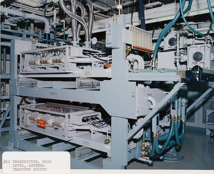
- C: High level waveguide switches (kludge), Room 248
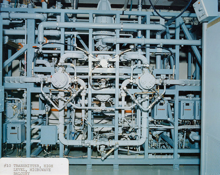
- 1036: Closeup view showing water cooled waveguides and one of the water cooled dummy loads (hat-like device at top center).
- 1104: Drawing with components labelled.
- 1068: Kludge on the microwave balcony as seen from the klystron room.
- 0088: Comments
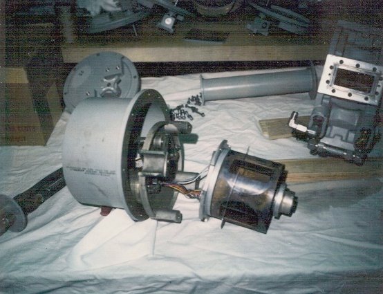
- 9002: High power waveguide switch damaged by water in the waveguide (Aug 1973).
-
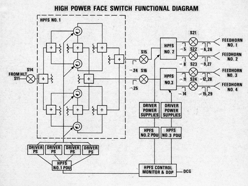
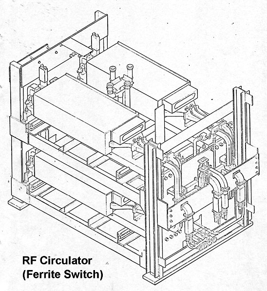
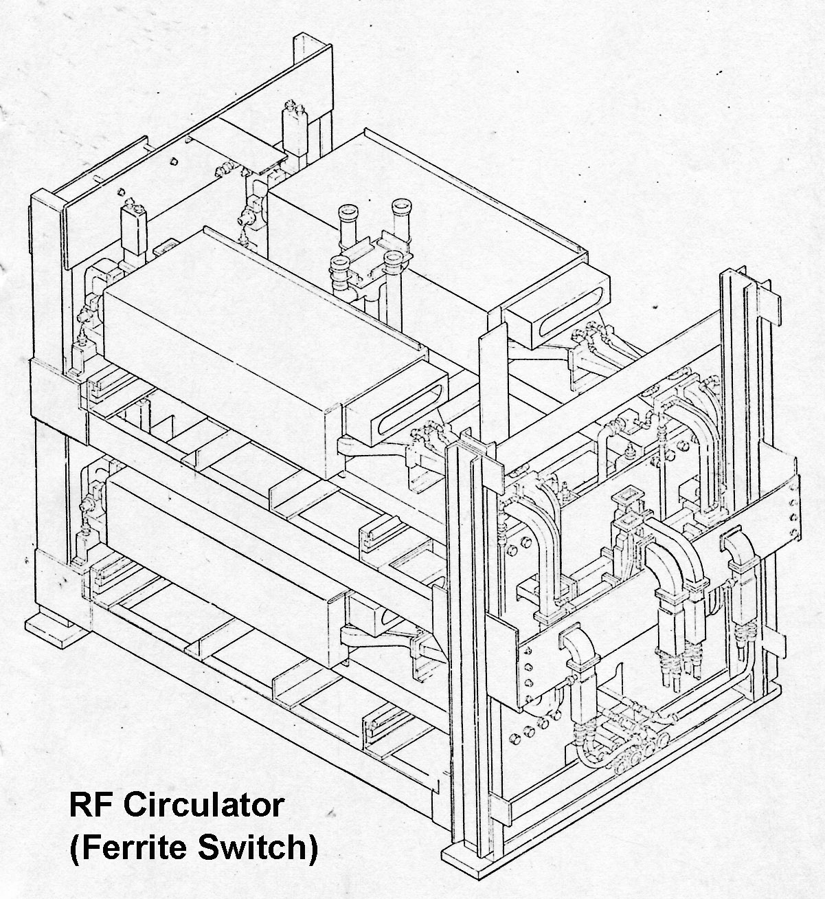
Under software control, this bank of three high power RF switches connected the combined output of klystrons to one of the four antenna faces.
- Although only one antenna face could radiate at a time, switching times were fast enough to make it appear that multiple faces were radiating simultaneously.
-
7358e: <$
- F: Microwave balcony, Room 248
-
1116e: <$
- B: Microwave balcony, Room 248
- D: Three antenna face switches (ferrite switches), Room 248
- 1113: High power face switch functional diagram.
-
7358e: <$
- F: Microwave balcony, Room 248
-
1116e: <$
- B: Microwave balcony, Room 248

-
V029: Looking down into the klystron room on level 1. <$
- Historic photo showing the microwave balcony from the klystron room.
- Comments from Ves Fulp about the noise level on the balcony.
- V028: Looking 180° from the previous photo. <$
- V030: Looking right on the balcony. <$
- V031: Looking left on the balcony. <$
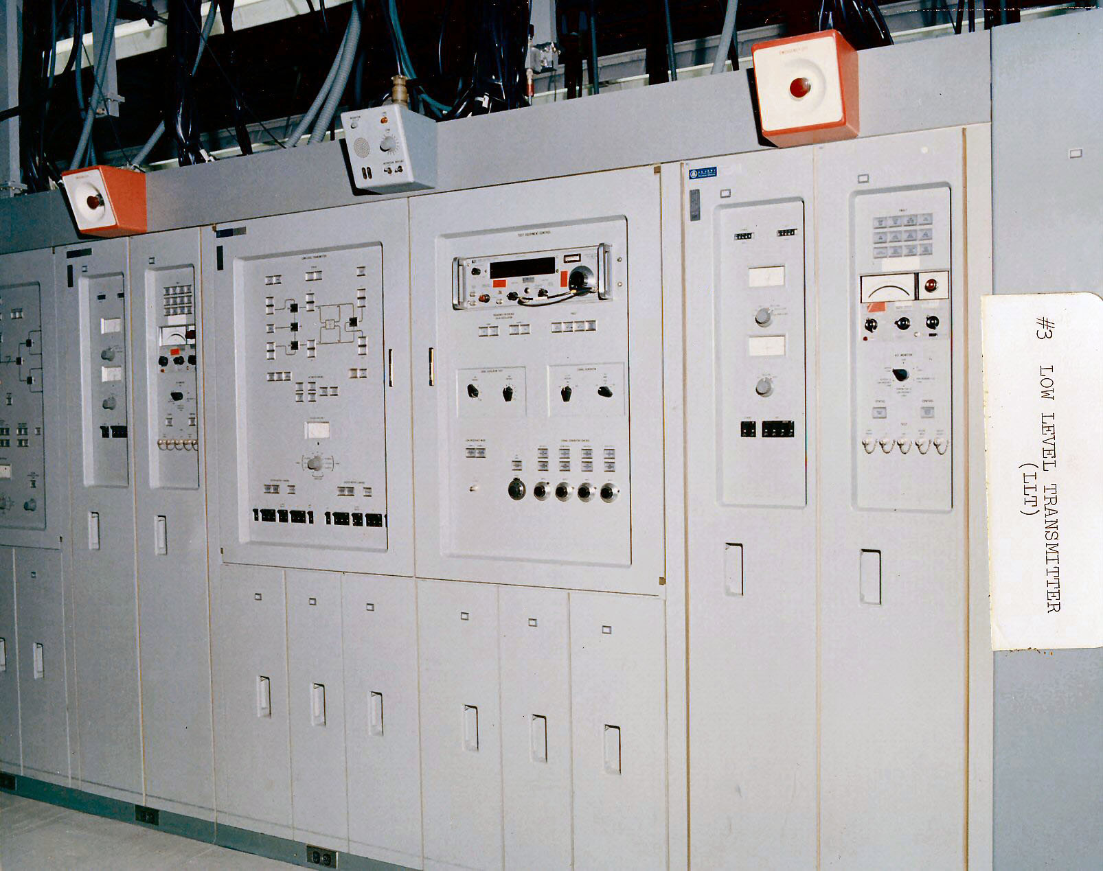
- Room 134.
- The large red buttons along the tops of the control panels were "Emergency OFF" buttons used to shutdown all low voltages and high voltages throughout the transmitter areas, including the firing of the "crowbars" to discharged the energy stored in the high voltage capacitors.
-
7356e, 1117e: <$
- B: Transmitter control room, Room 134
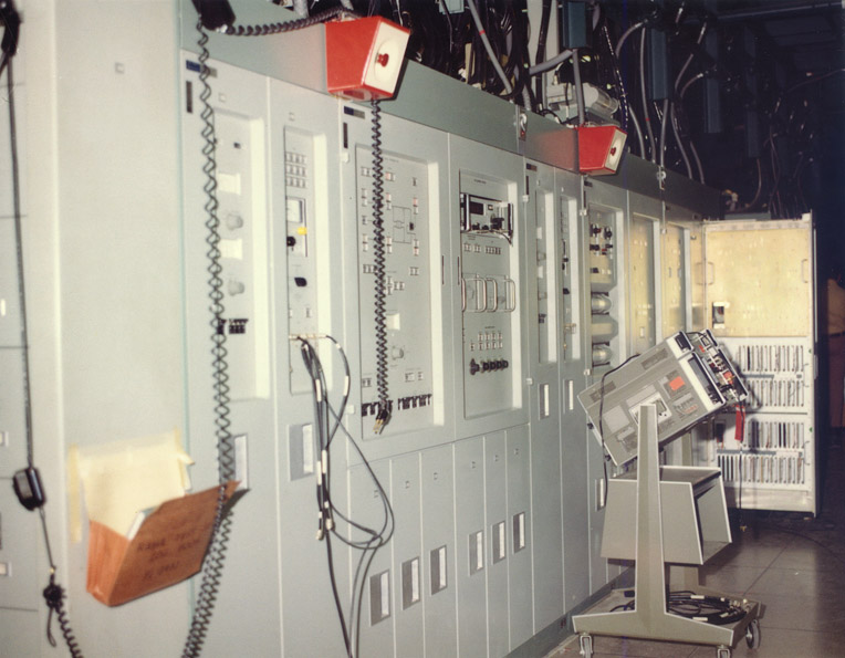

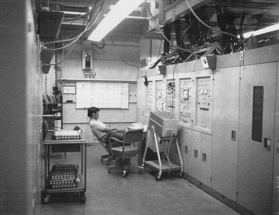
- 0071: High level transmitter (HLT) control panel.
- 1067: Low level transmitter (LLT) control panel.
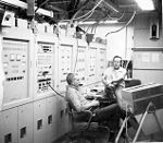
- A000: Bill Elrod (l) and Ves Fulp (r) relaxing for once in the MSR Transmitter Room - circa 1974.
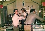
- I018: Transmitter control group.
- 9005: Left to right: Paul Palsinski (Raytheon), Paul Tudor (WECO), Bob Neighbors (Raytheon).
- 9003: Left to right: Joe Gaye and John Haley (Raytheon Wayland).
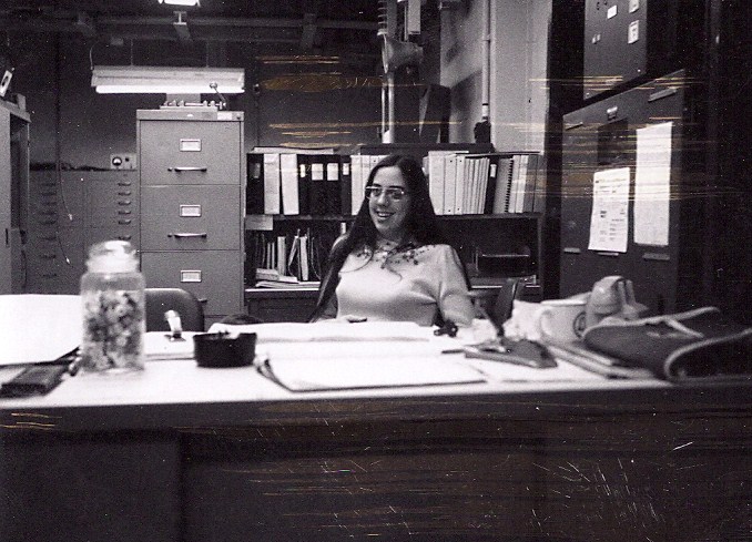
- A002: Miss Transmitter Room, Pamela Bodenheimer - circa 1974. Comments
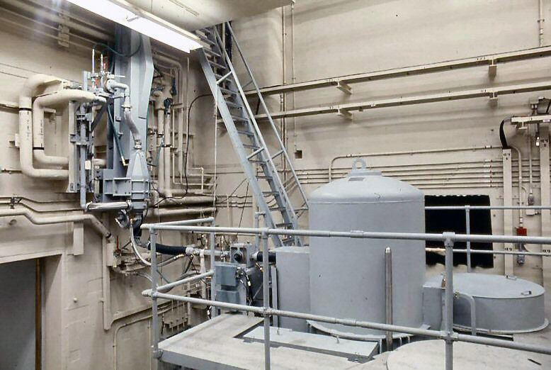
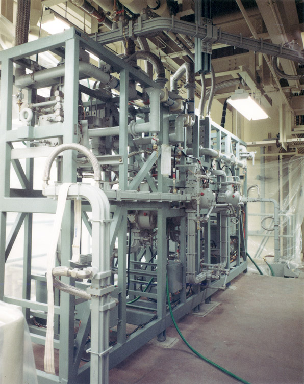
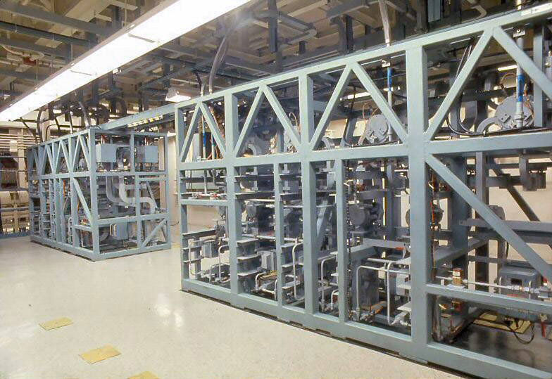
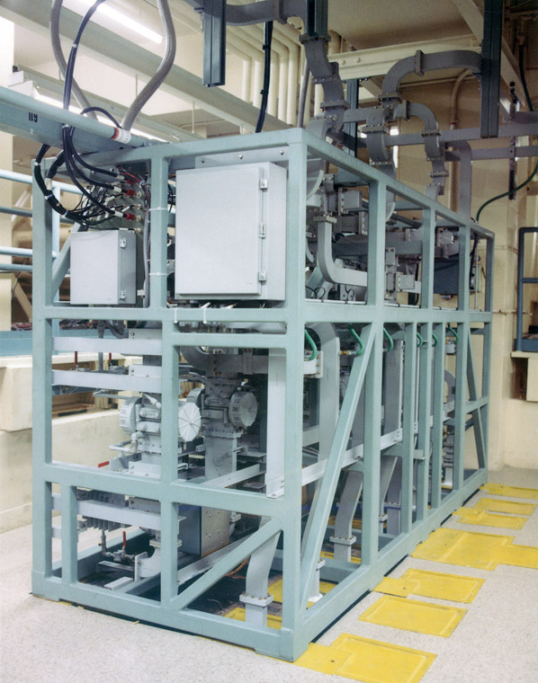
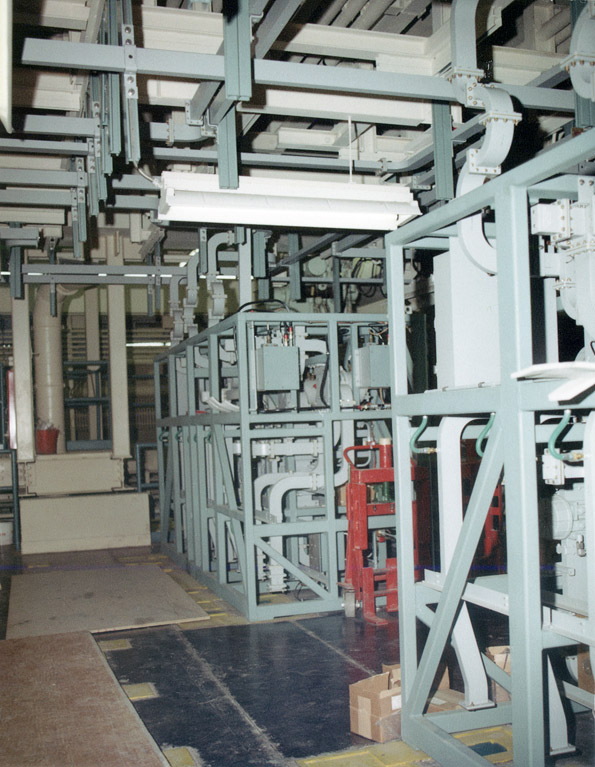
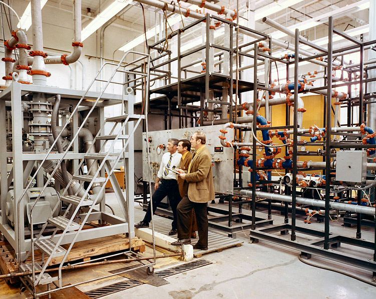
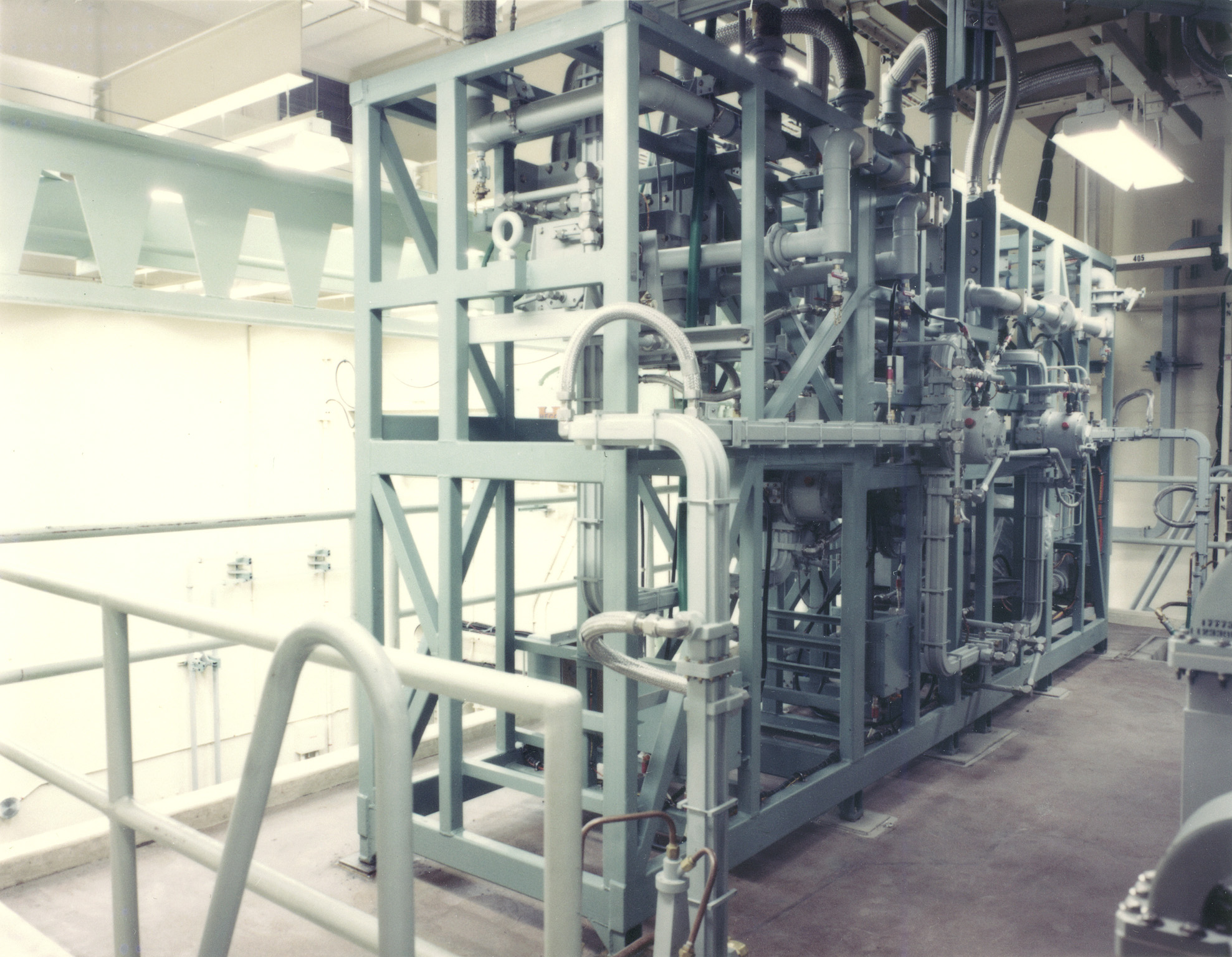
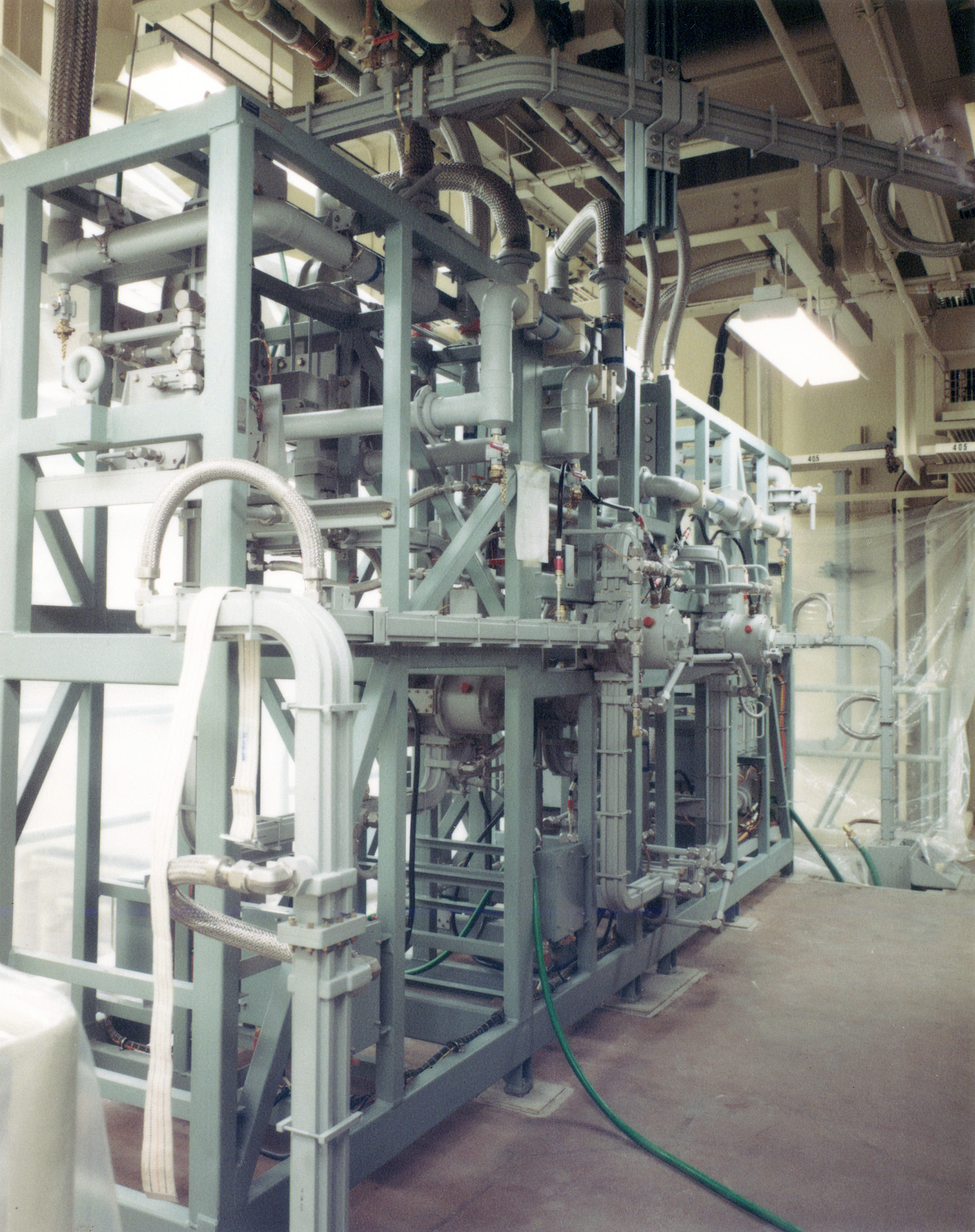
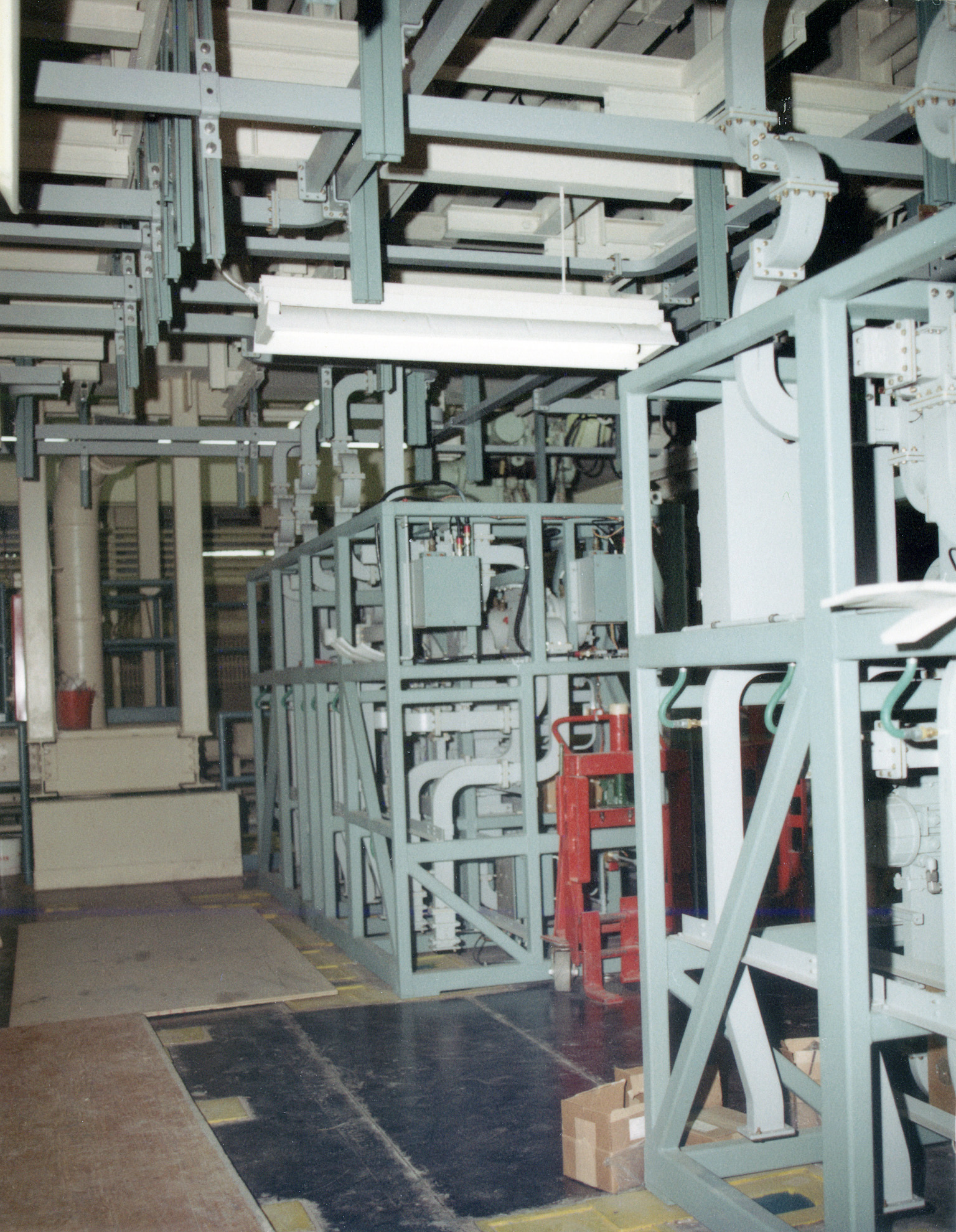
- Rooms 130 (transmitter cooling room), 131 (oil pumping room).
- Contained equipment for the purification, filtering, circulation, and heat exchanging of the high purity water, dielectric oil, and dielectric gas (SF6) used by the transmitter.
-
7356e, 1117e: <$
-
D (Room 130): Transmitter cooling room
D (Room 131): Oil pumping room
-
D (Room 130): Transmitter cooling room
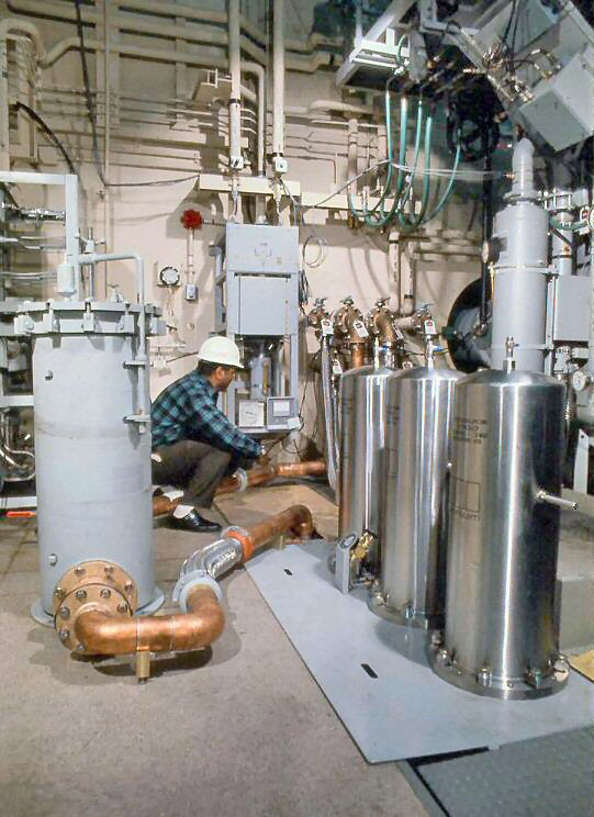

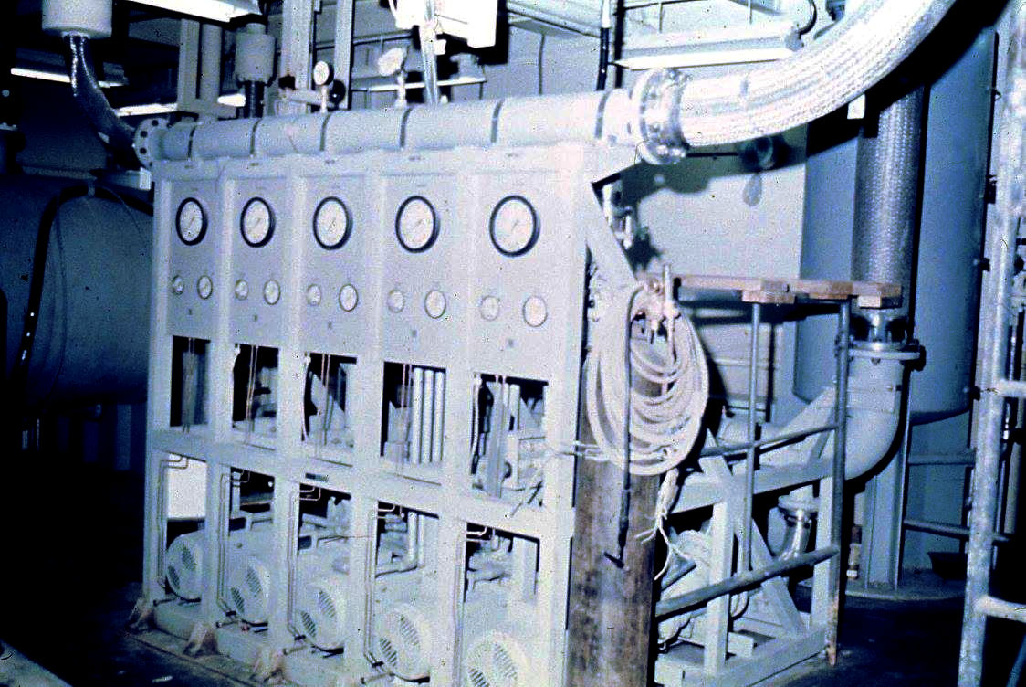
- 1075: Cooling water purification.
-
1063: BB shot
- During attempts to resolve a problem with the klystron cooling water flow, these were used as copper pellet scavengers to remove sulfides from the water.
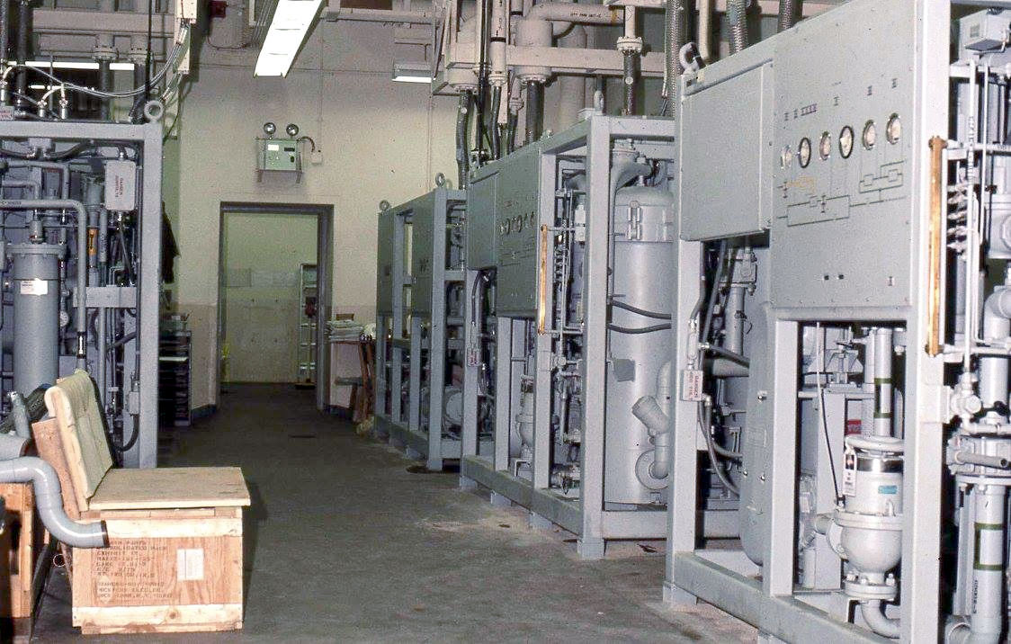
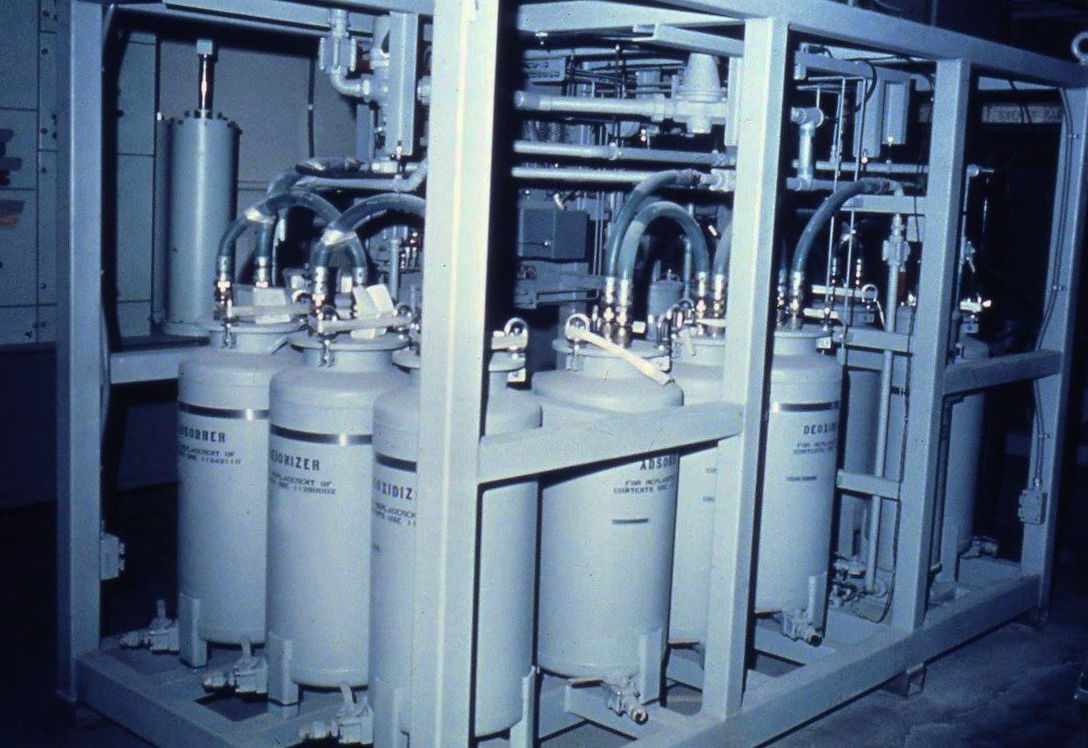
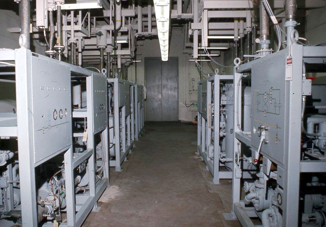
- I012-I014: Transmitter cooling equipment.
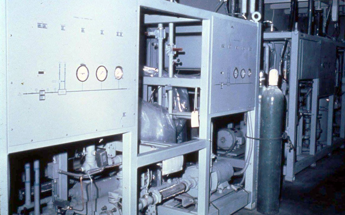
- I015: Transmitter oil cooling system.
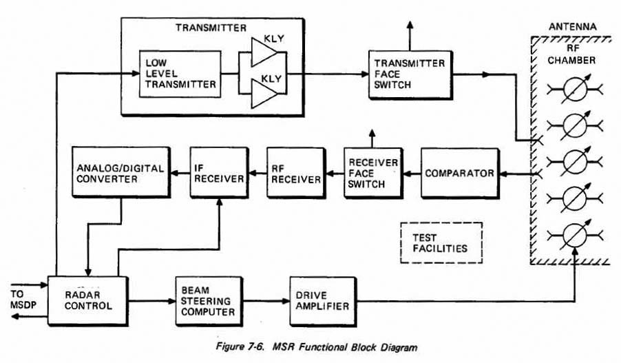

- 8001: MSR functional block diagram.
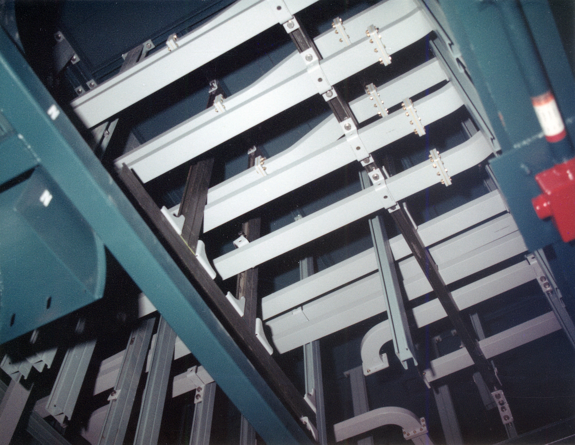
- 0033: Low power waveguides (without water cooling channels).
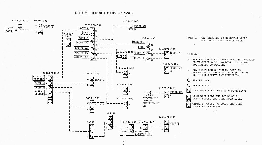
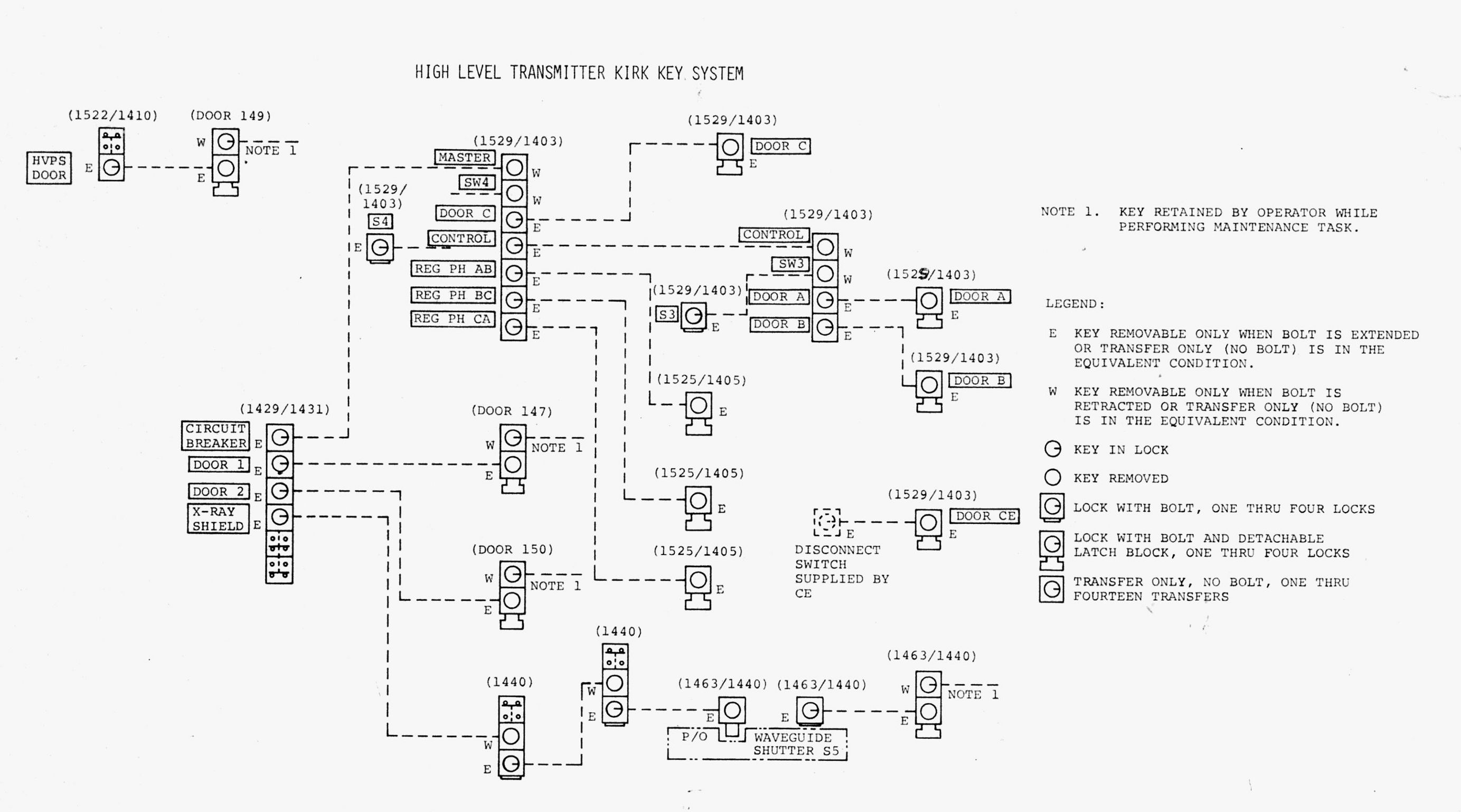
- 1112: Kirk key system diagram, high level transmitter.
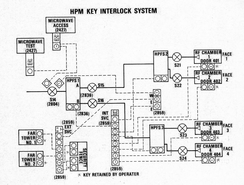
- 1114: Kirk key system diagram, high power microwave area.
- I000: Room 114: antenna cooling system.