MSR / MSCB Photos: Interior
Anechoic Chamber
- Photo Sources:
-
0nnn: Anonymous WECo engineer -
1nnn: Ves Fulp -
9nnn: Don Felten -
Annn: A_.ndrew / Shutterstock -
Innn: Clint Esckilsen via Facebook (3)
-
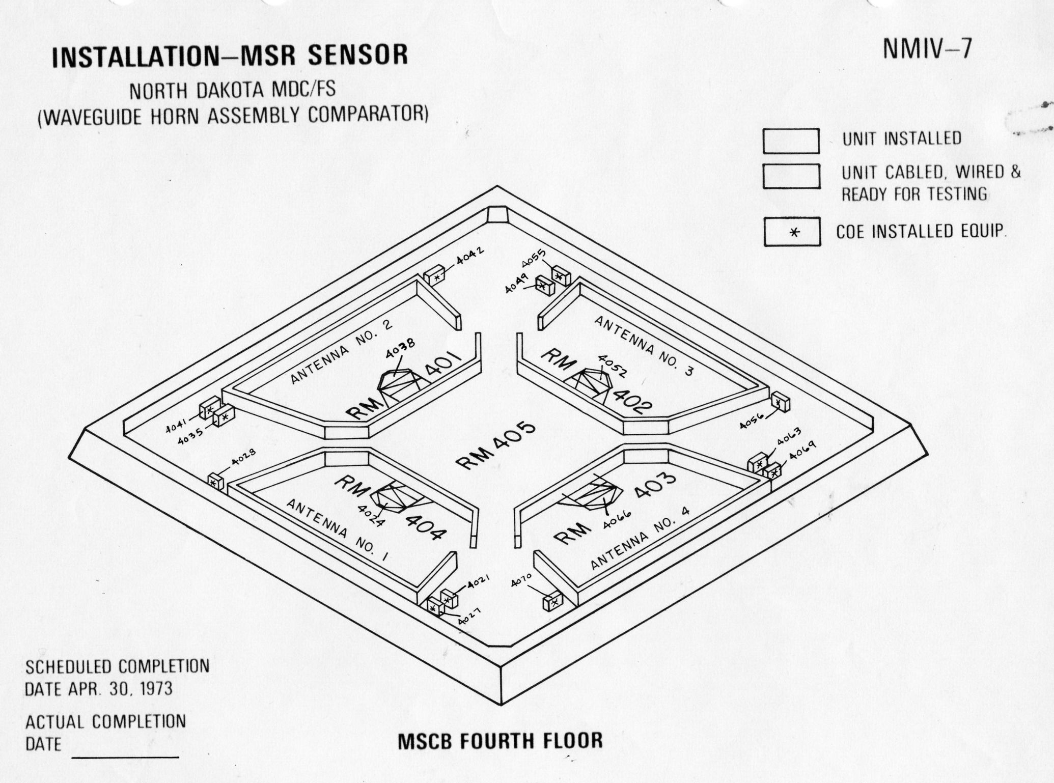
MSCB level 4, rooms 401, 402, 403, 404.
(There was a chamber behind each MSR antenna face.) - Also known as the RF room or RF chamber.
- Comments
![]() (opens in a new window)
(opens in a new window)


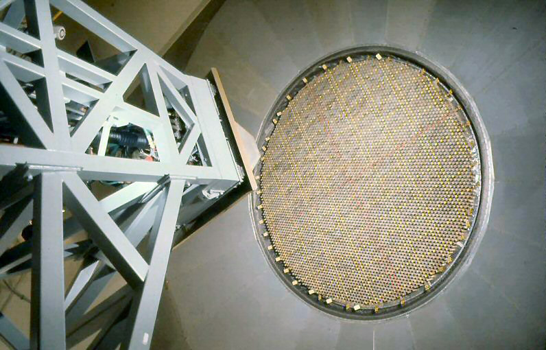
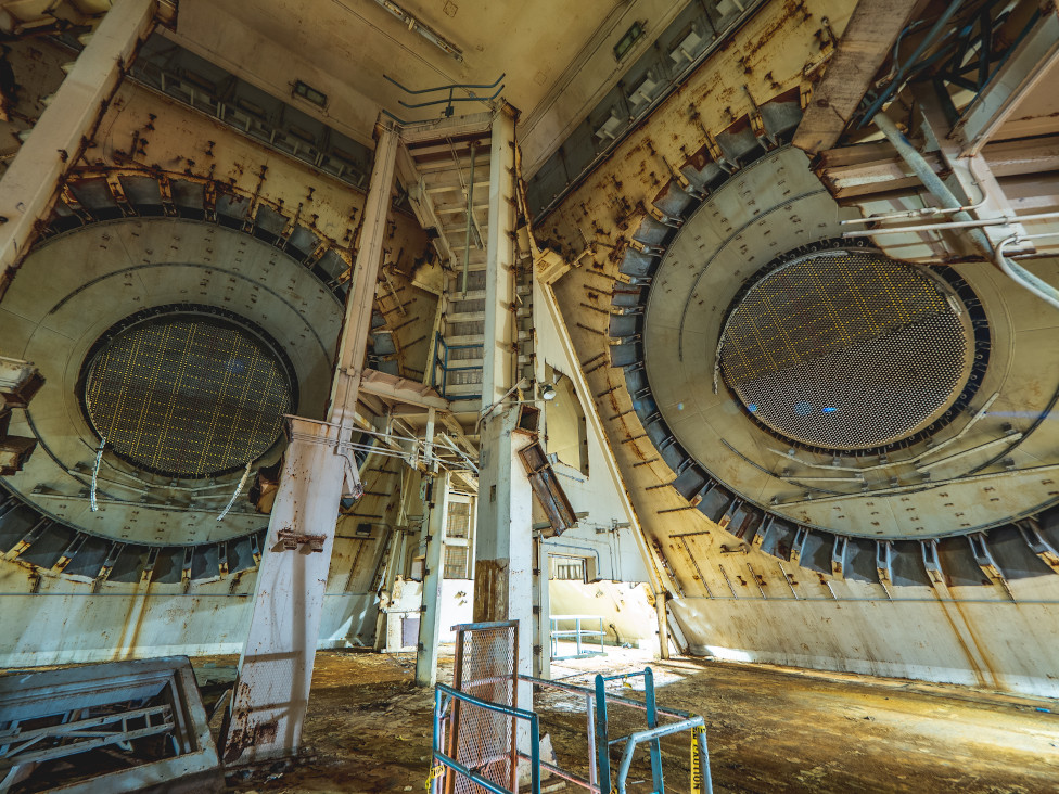
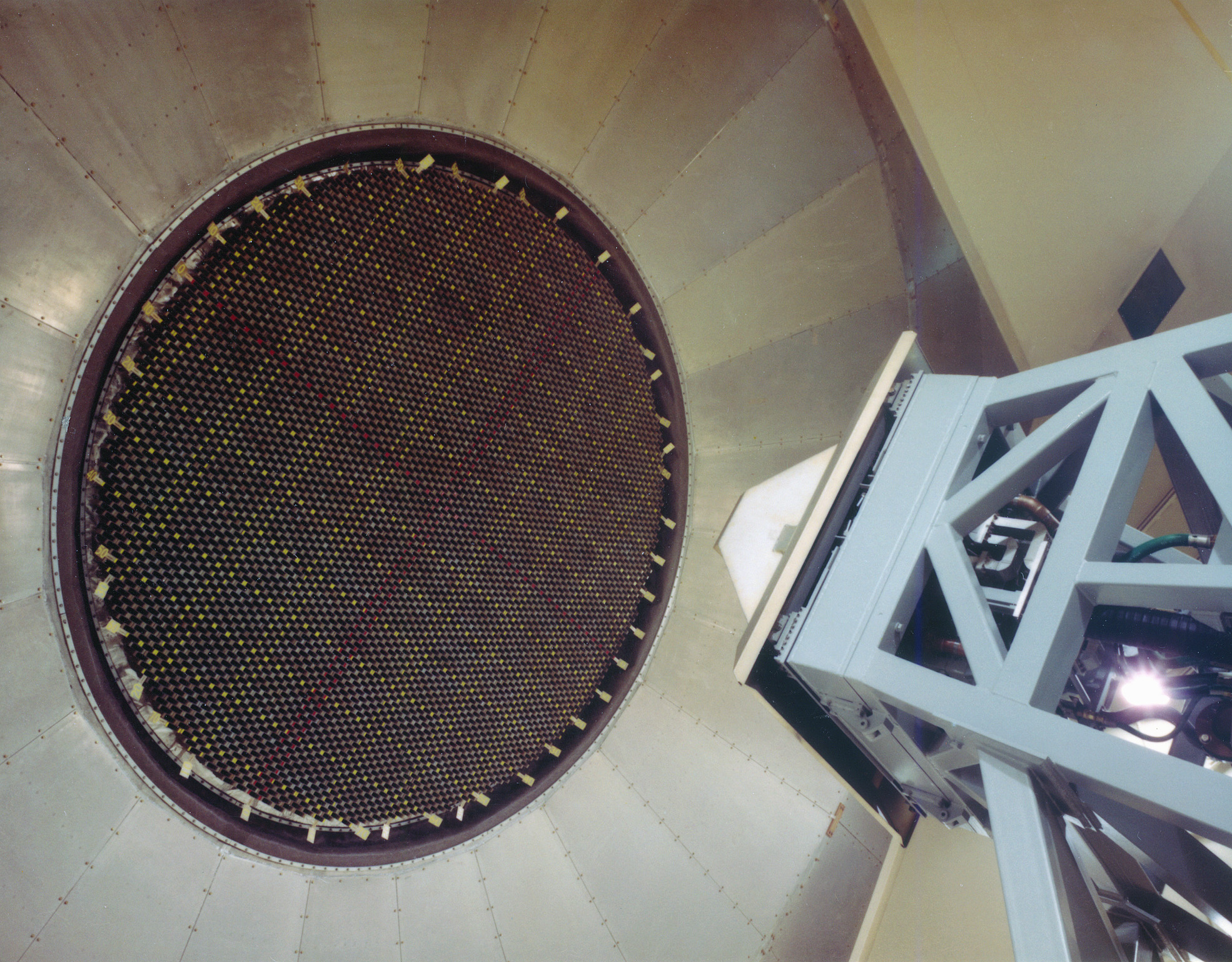
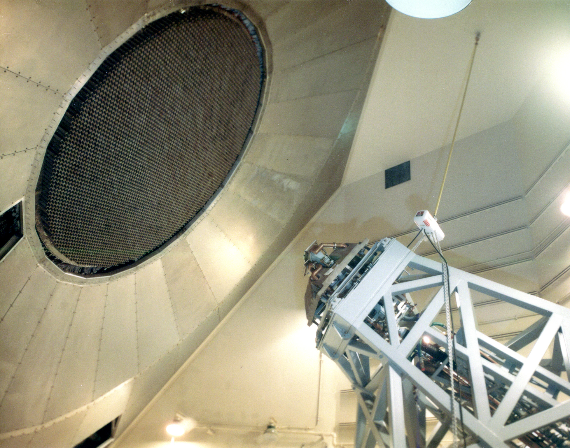
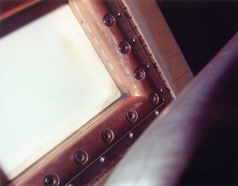
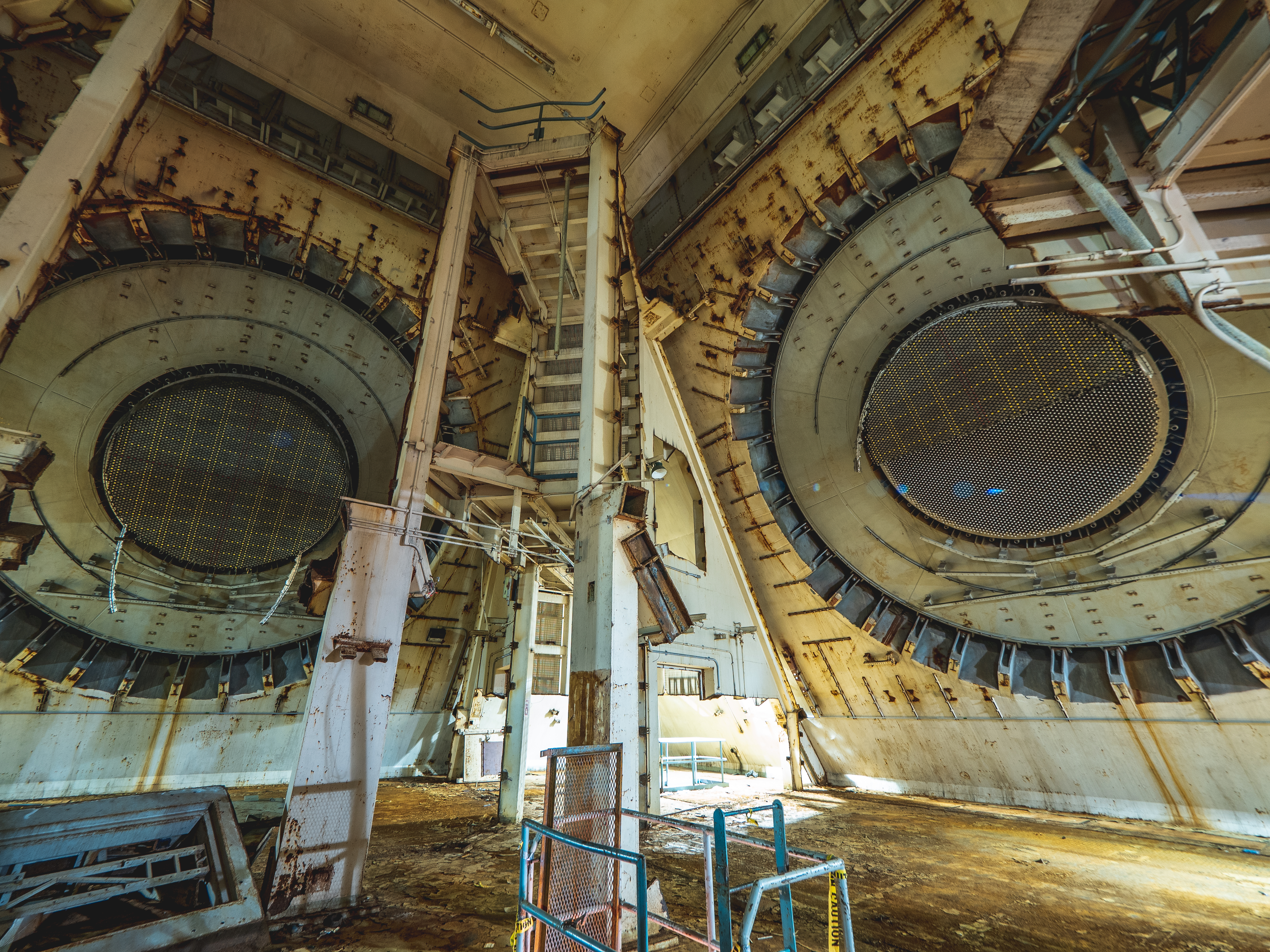
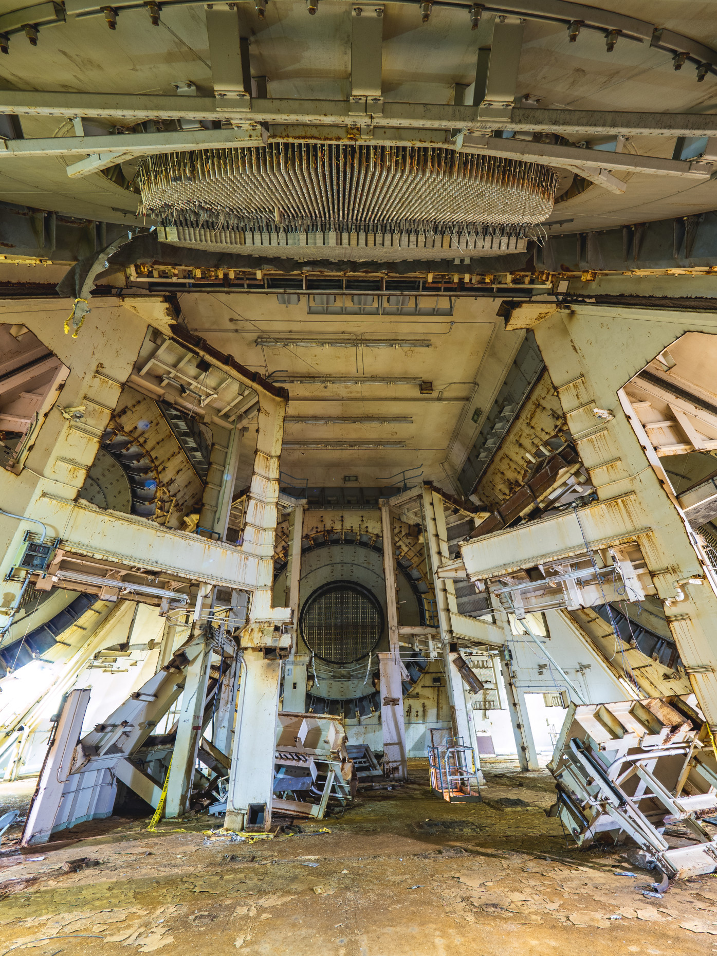
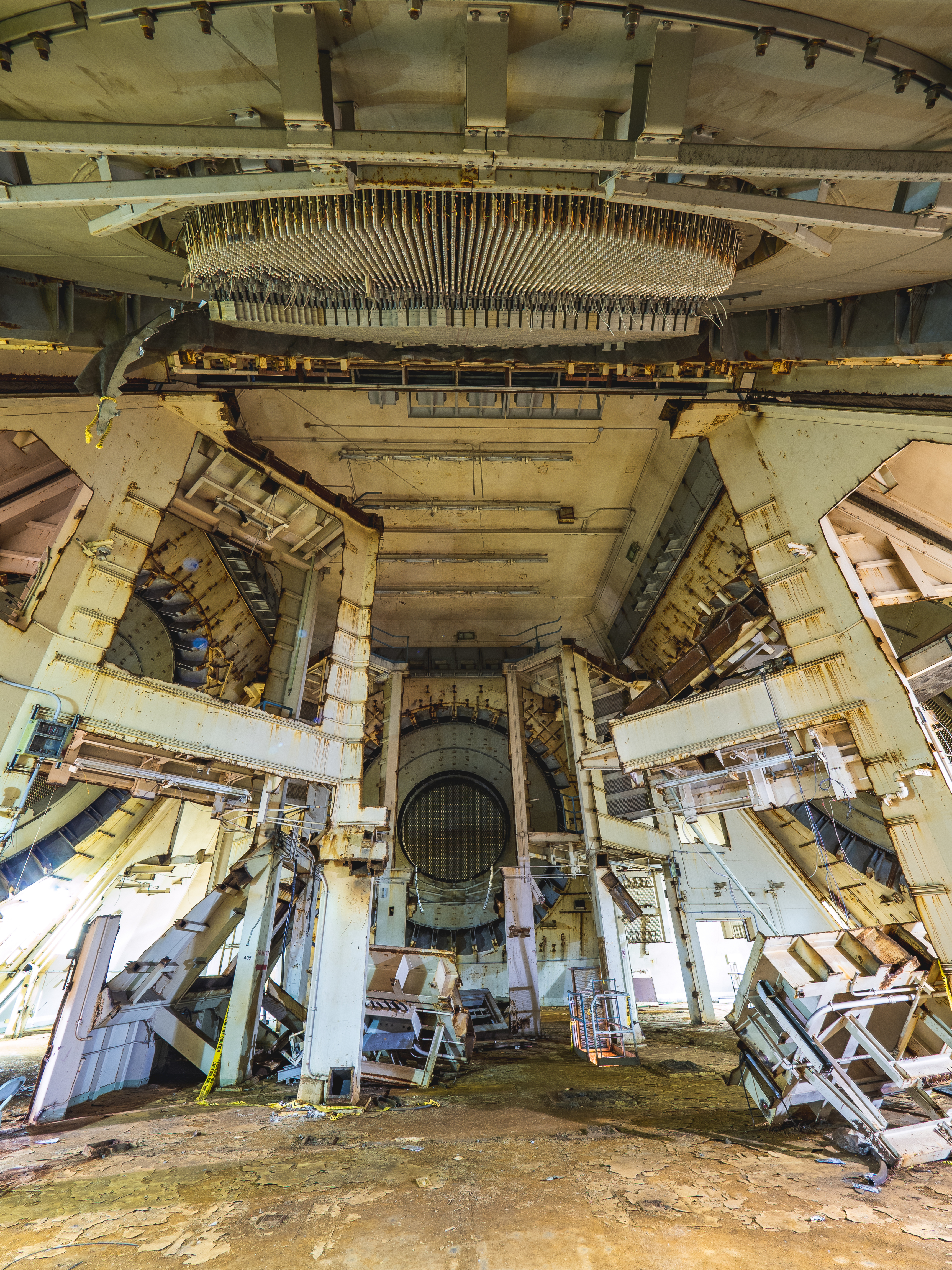
- 0026, 1017: Antenna array elements were rear-illuminated by the feedhorn assembly. Comments
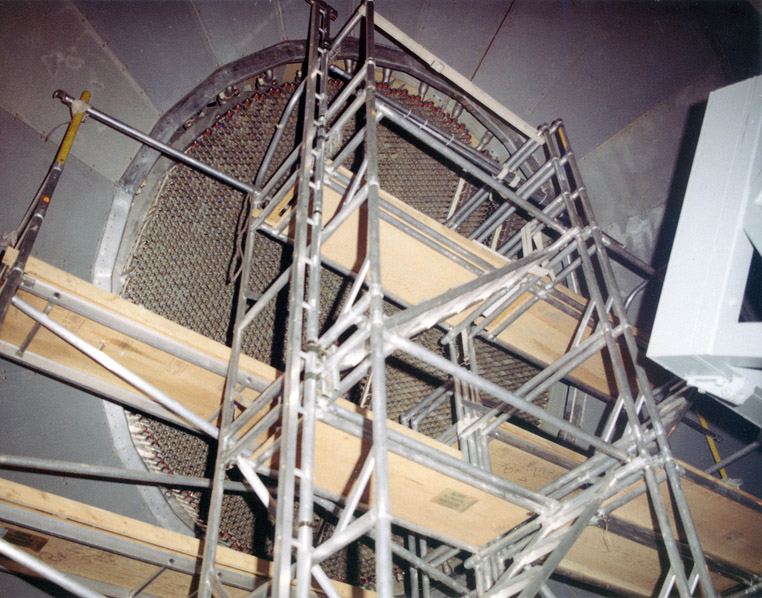
- 0029: Scaffolding in place during antenna installation.

-
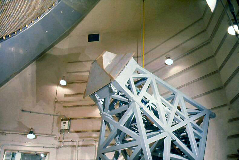
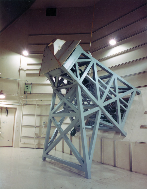
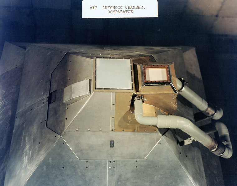
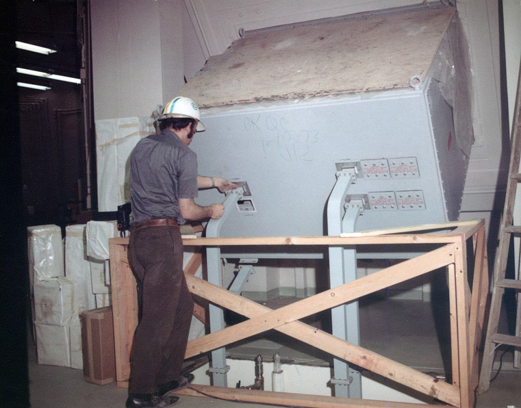
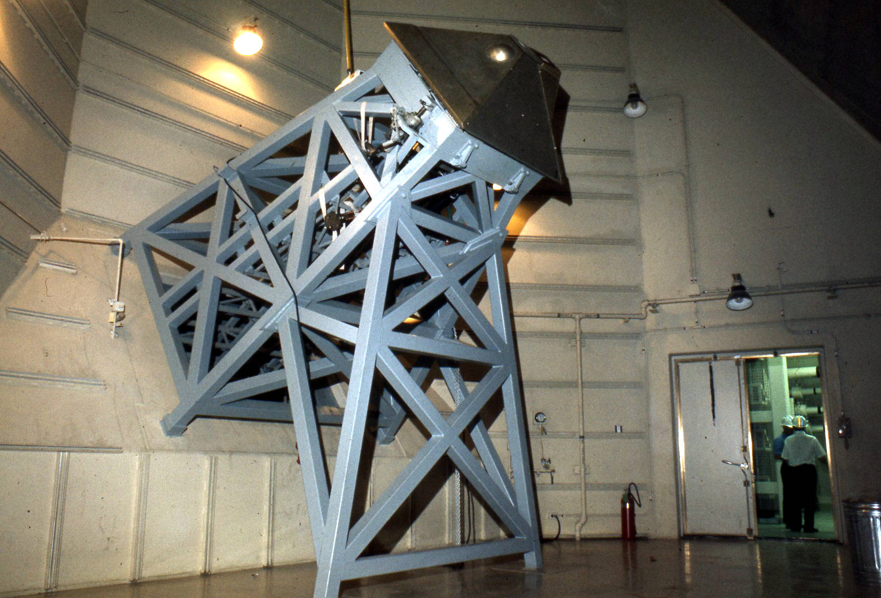
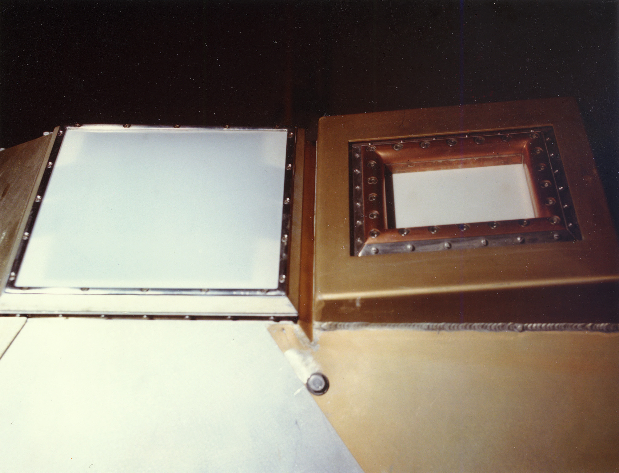
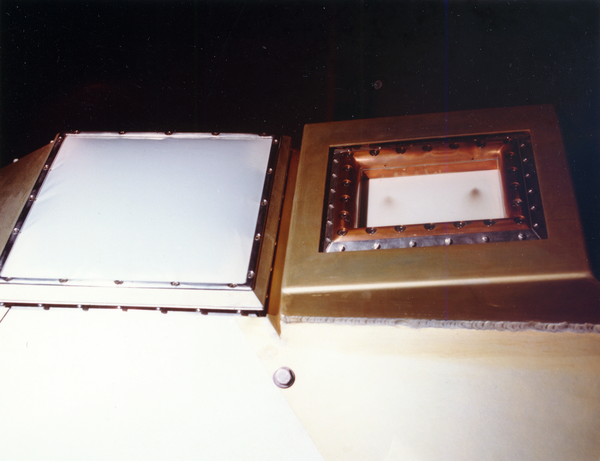
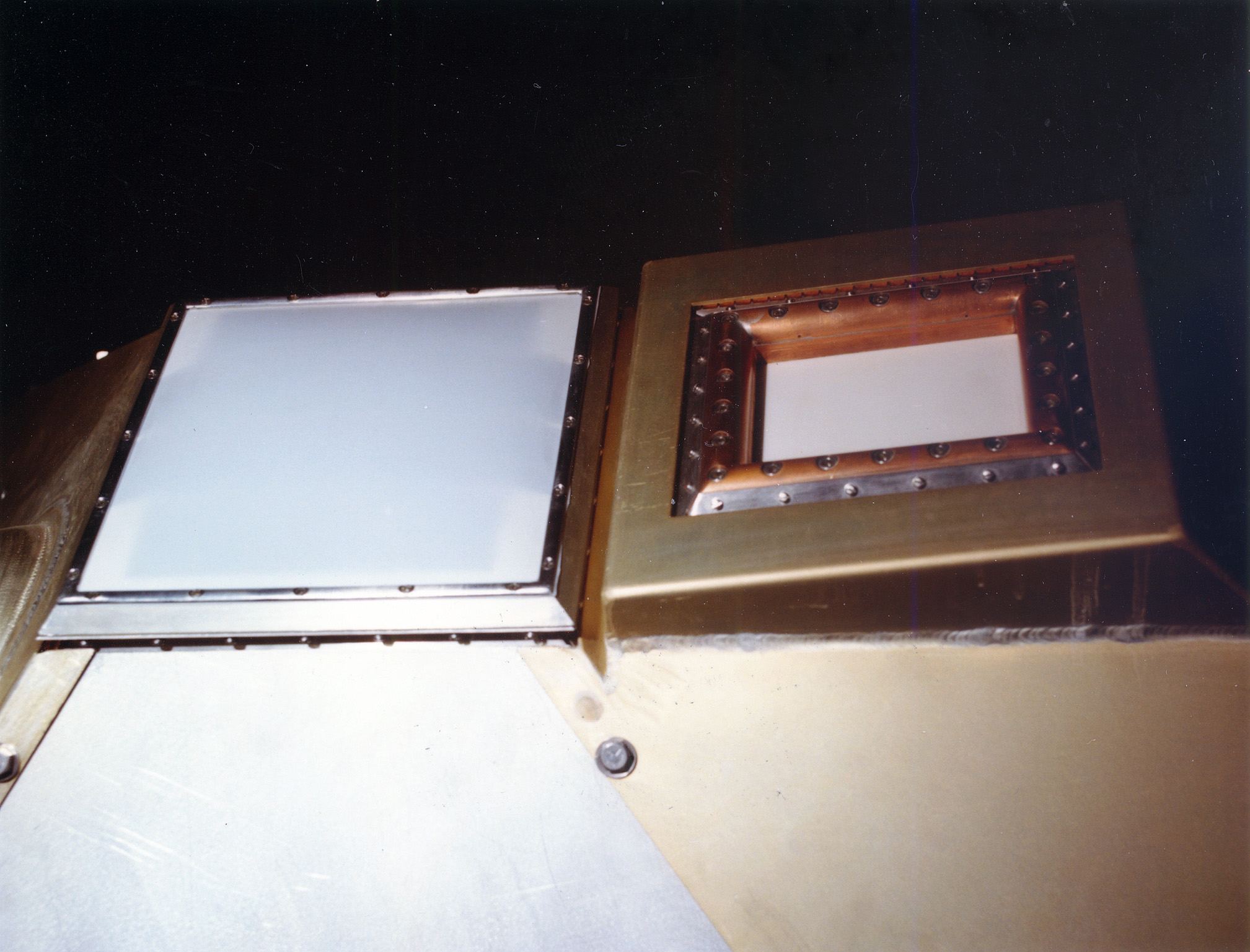
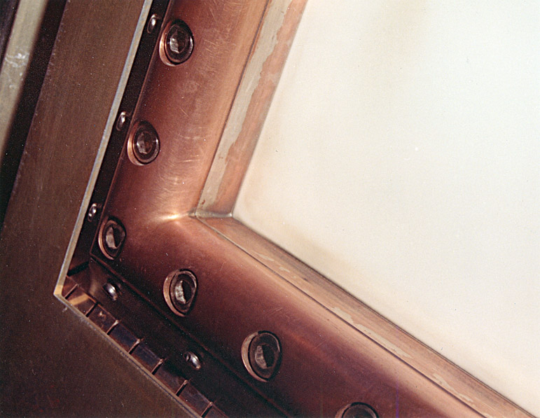
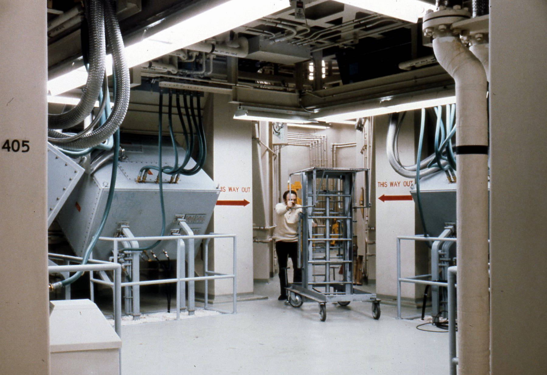
1019: The "business end" of the antenna feed horn.
- Receive antenna window is on the left, transmit antenna window is on the right.
- The comparator (in photo label) is the first component of the MSR receiver.
-
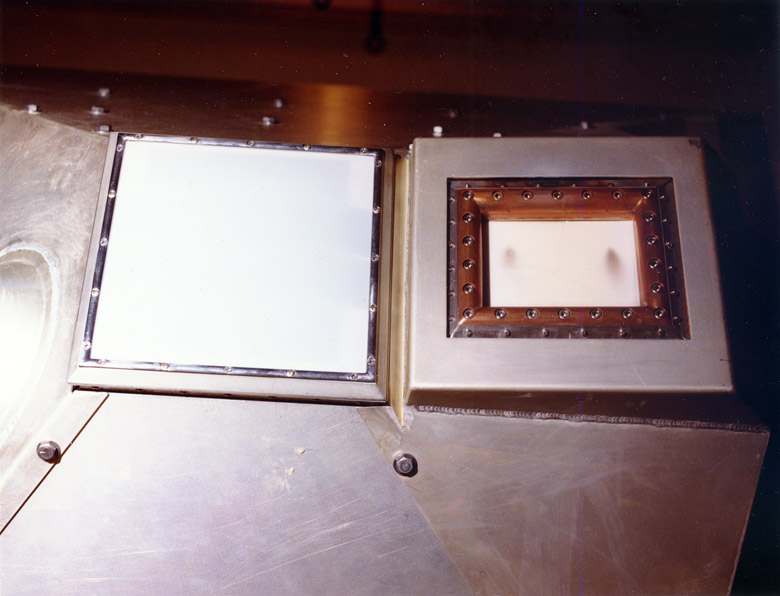
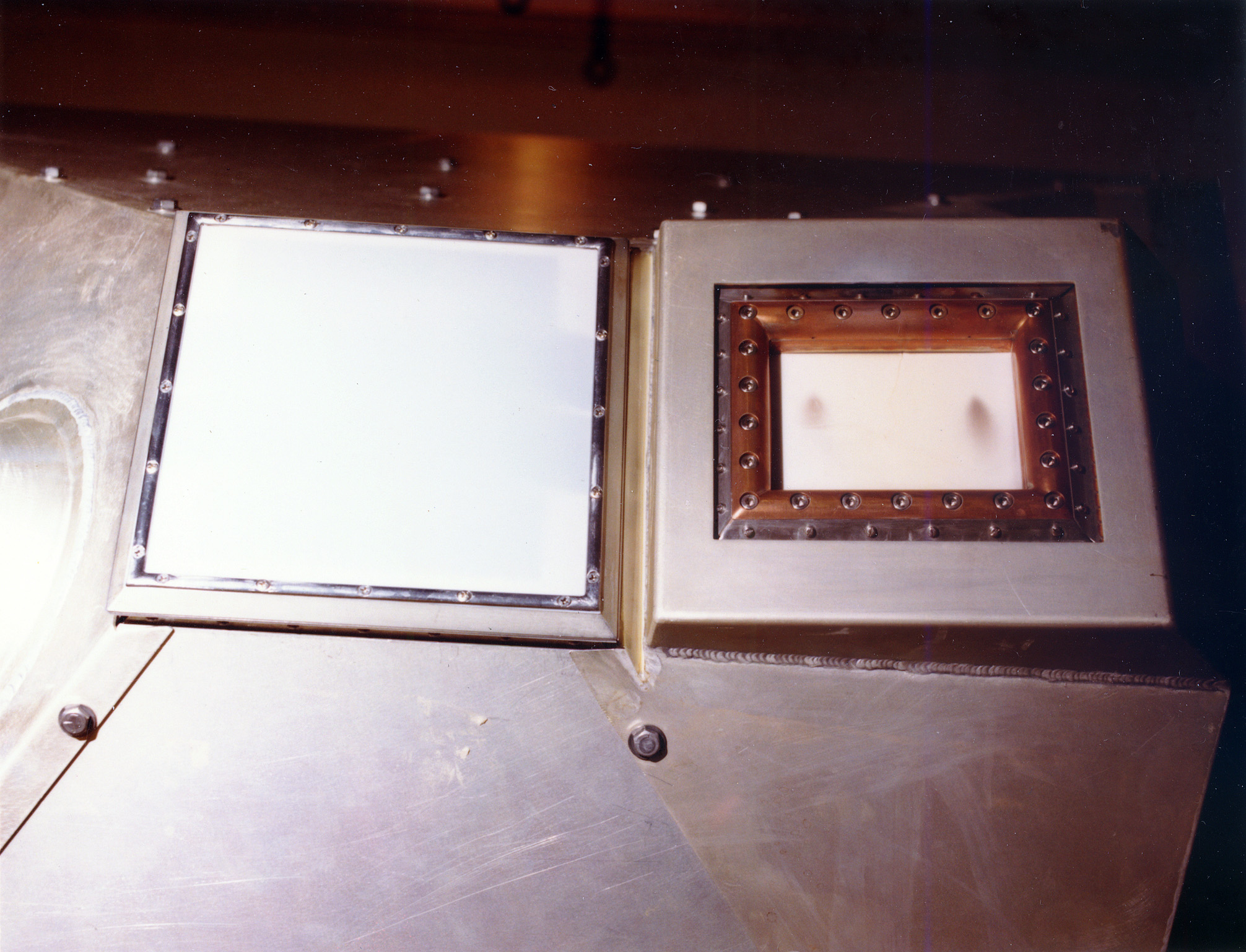
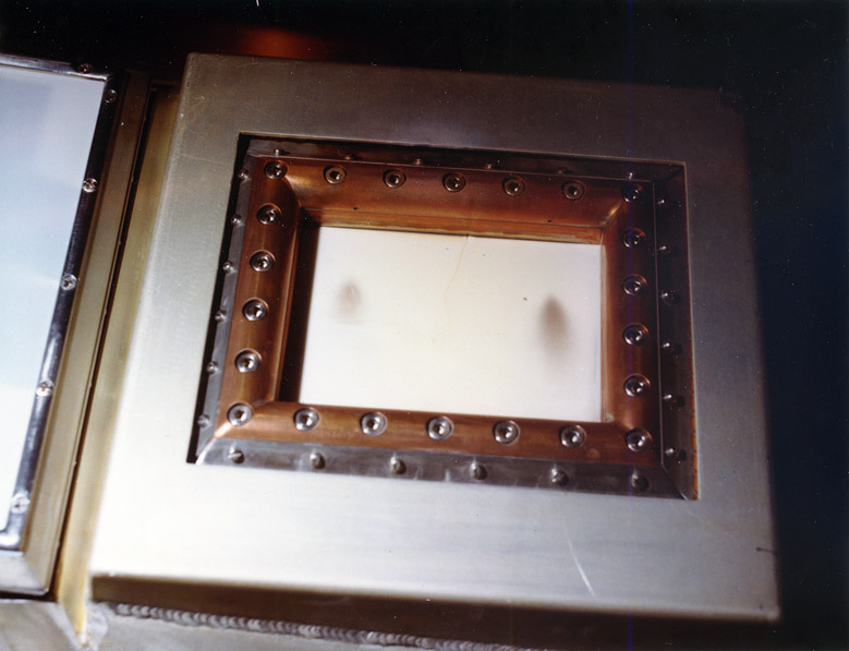
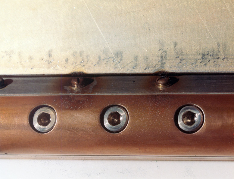
0009: Closeup of the receive and transmit antenna windows.
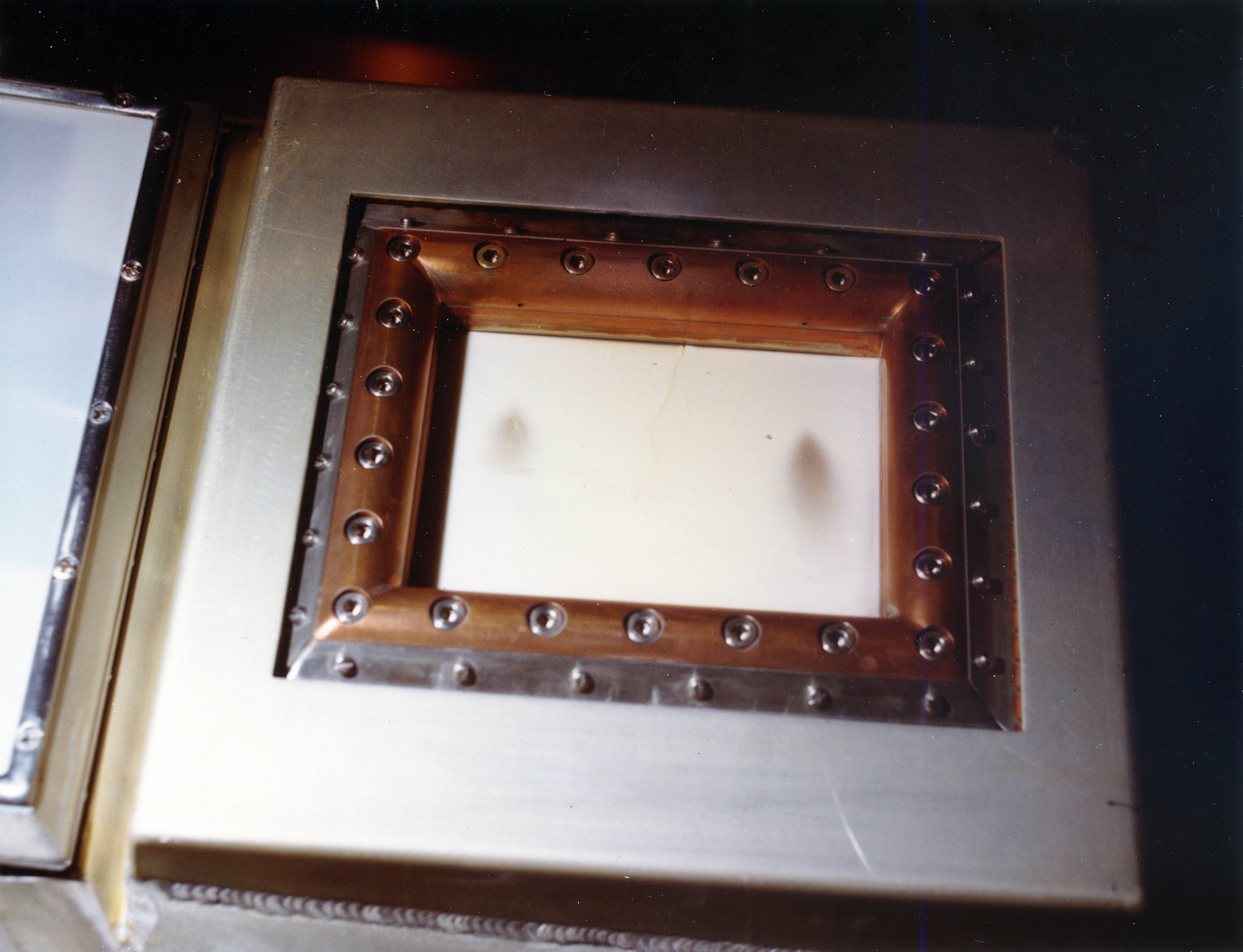
- Transmit window shows smudges from burns or arcing, which must be cleaned with Everclear before further radiation. (Ves Fulp)
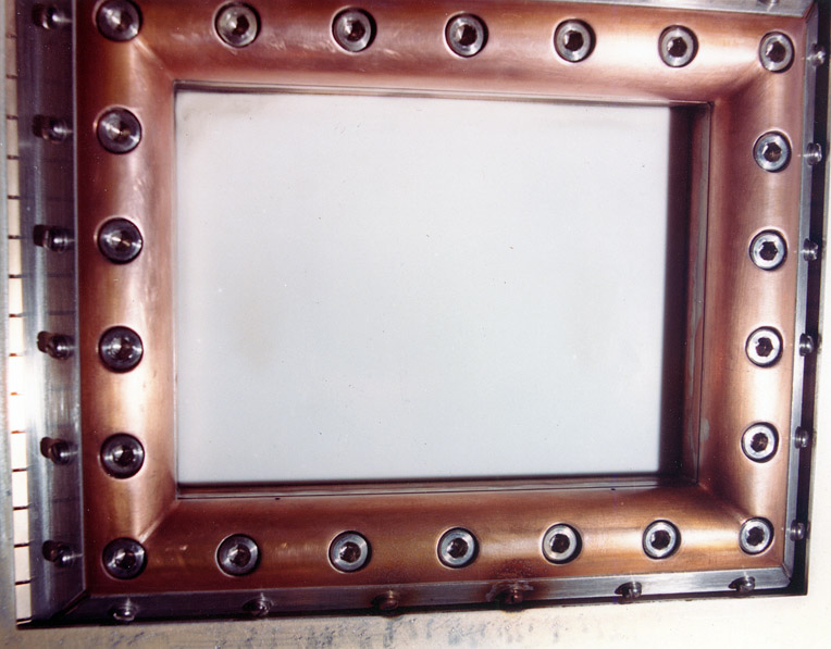
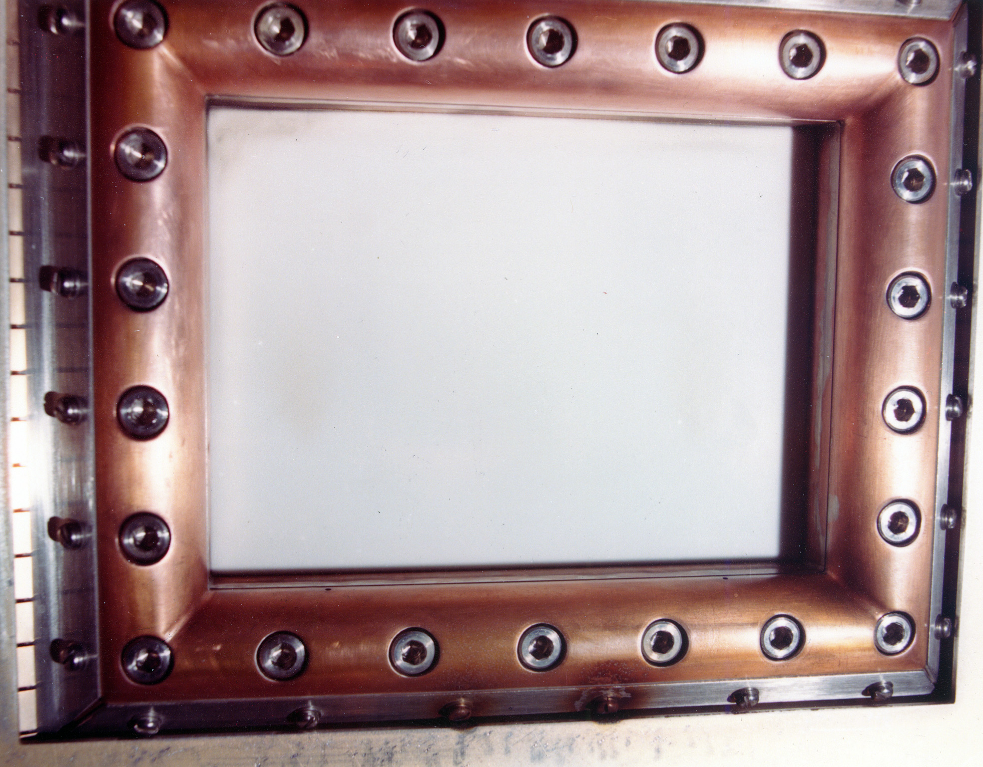
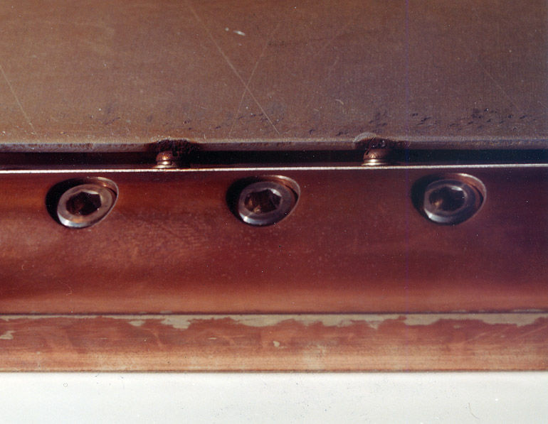
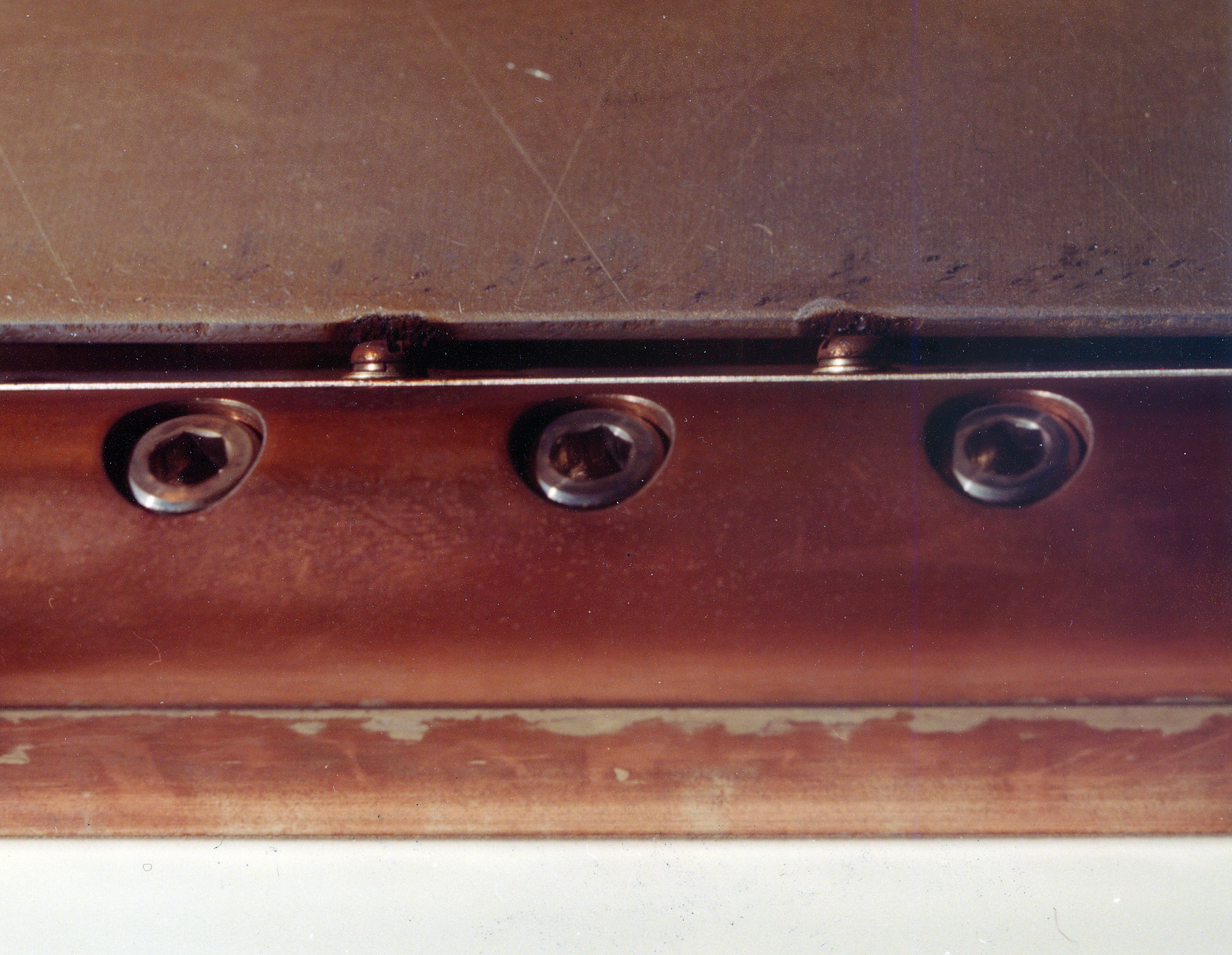
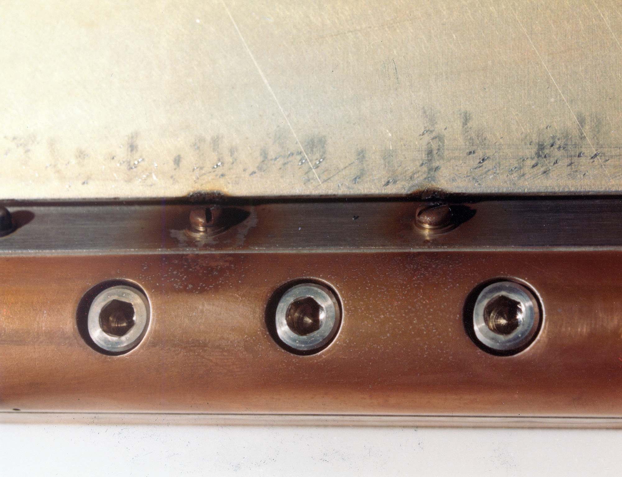
- 0012: Closeup of the transmit antenna window.
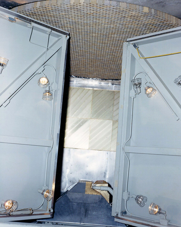
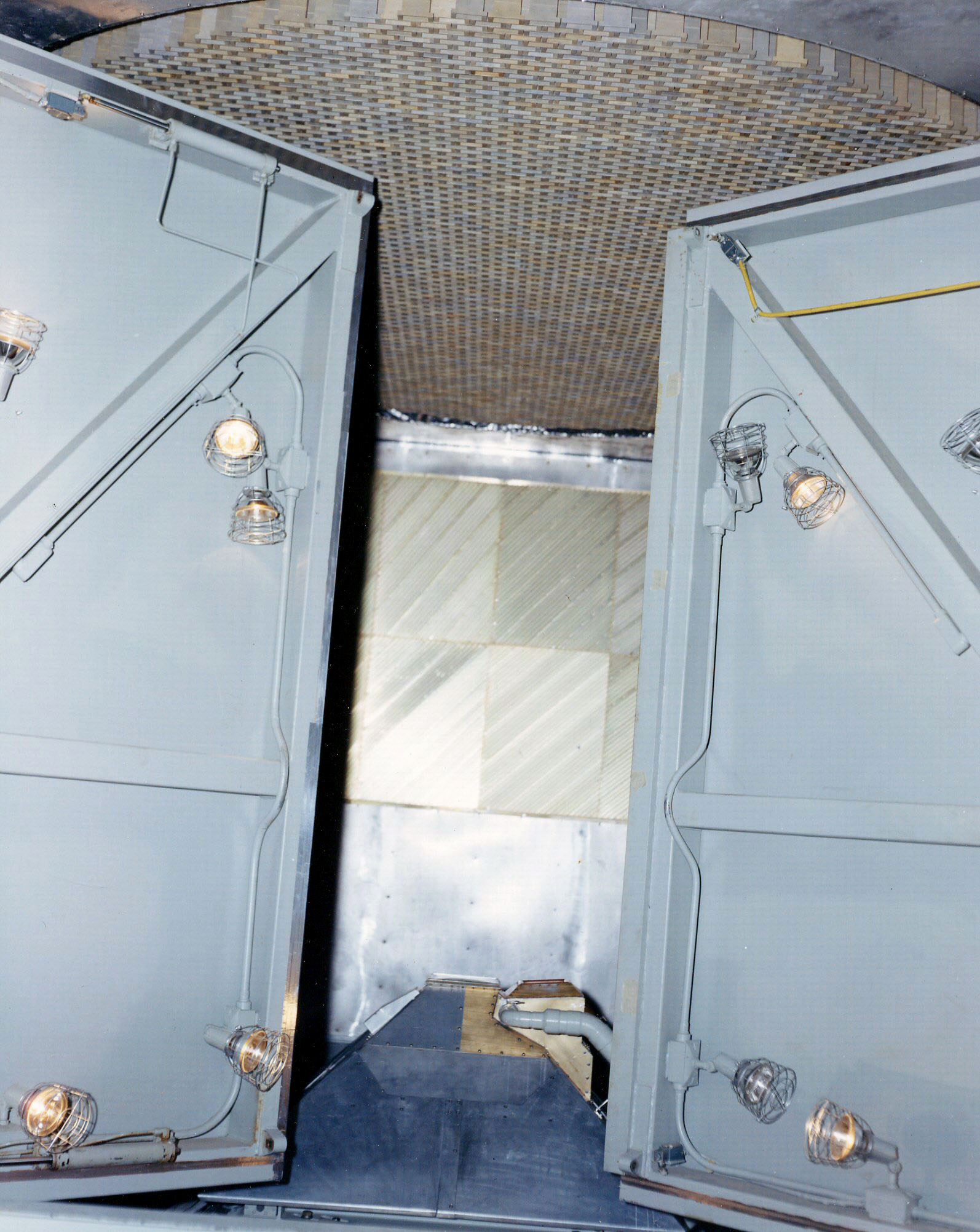
- 1020: Doors leading into the anechoic chamber.
-
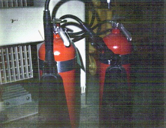
9001: Fire Extinguishers
- Normal one (left) and one that was in the MSR antenna chamber during full power operation (note melted handle).

-
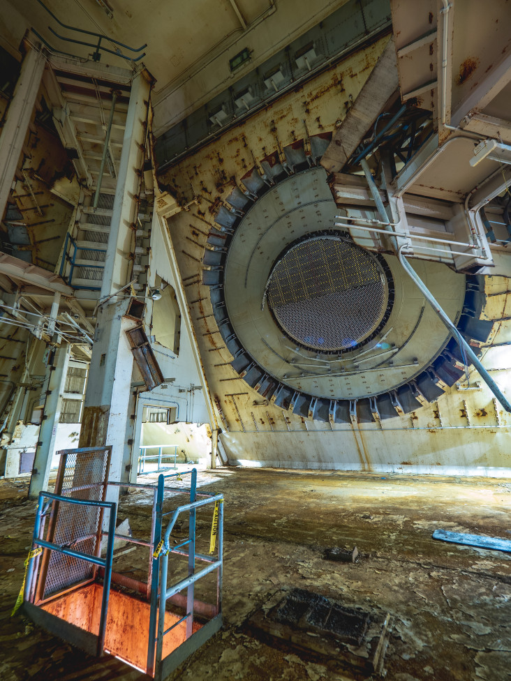
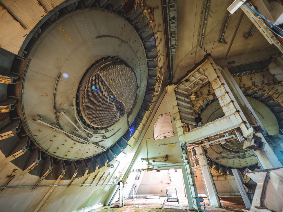
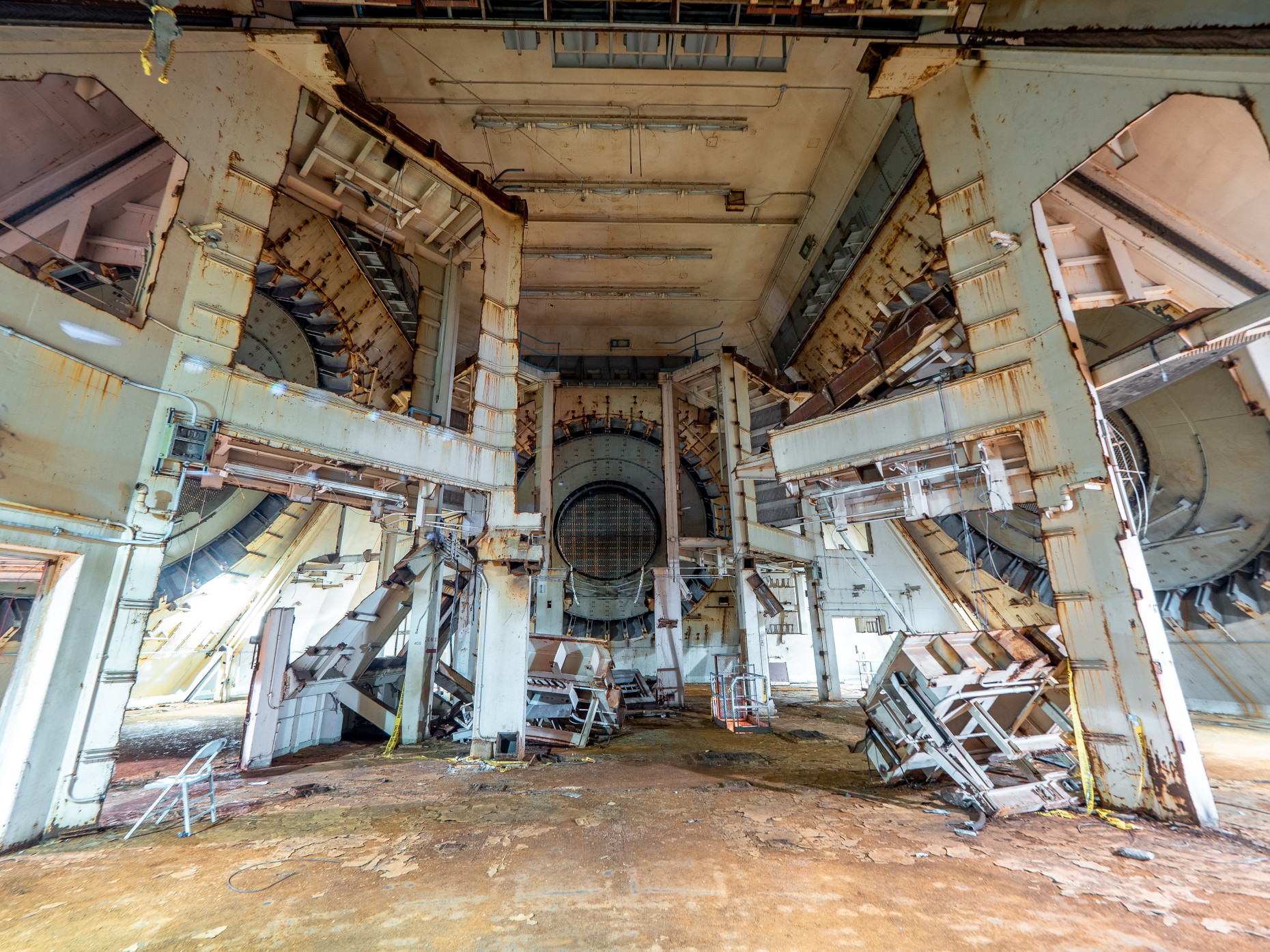
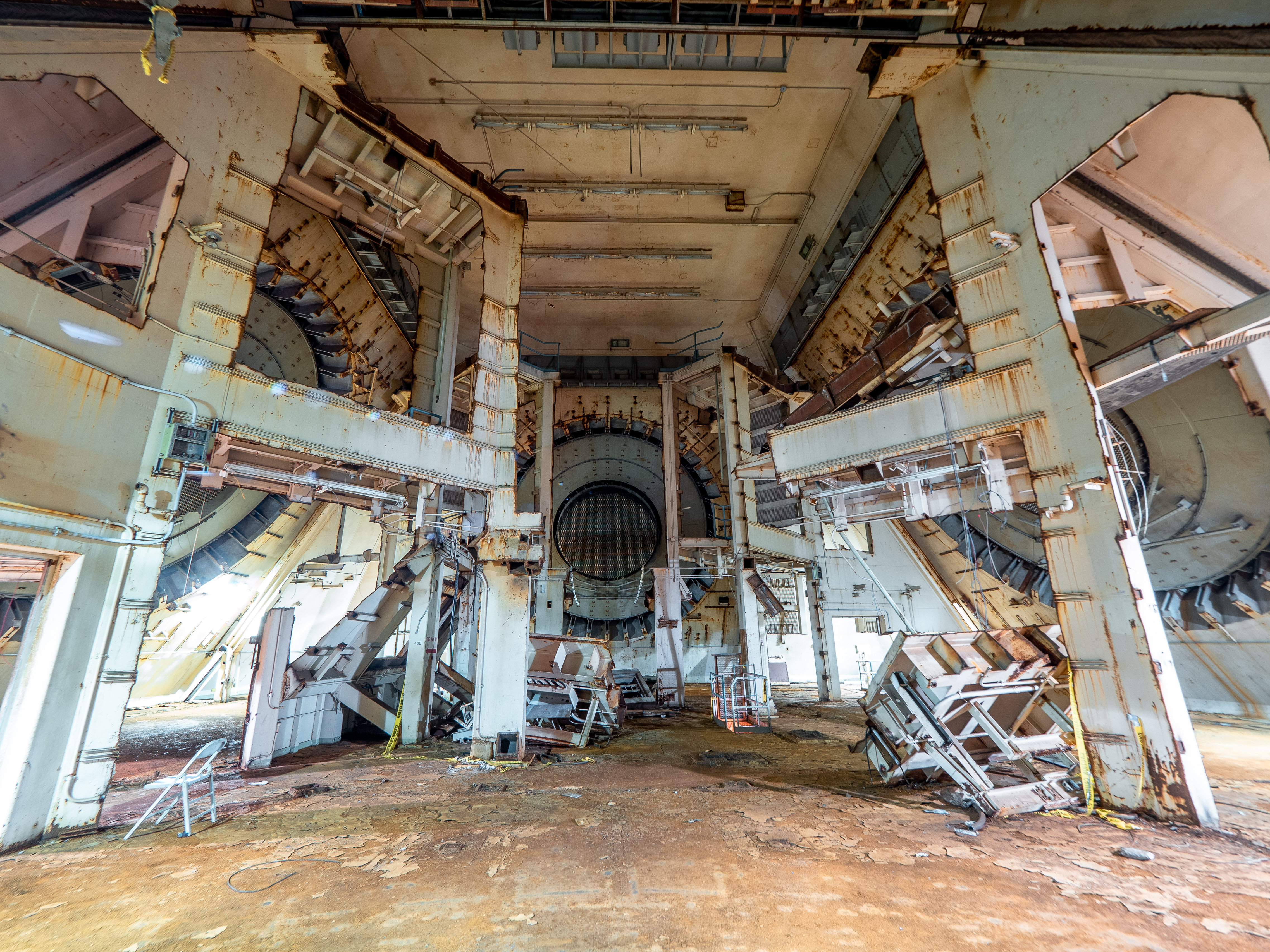
A202 - A206: Level 4 room 405, recent photos (see diagram 1115 below). <$
- The partitions dividing the rooms are gone.


-
0025: Transmit and receive waveguide penetrations into the anechoic chamber during installation.
- This is on the other side of the wall from the feedhorn assembly.
-
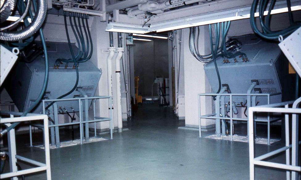
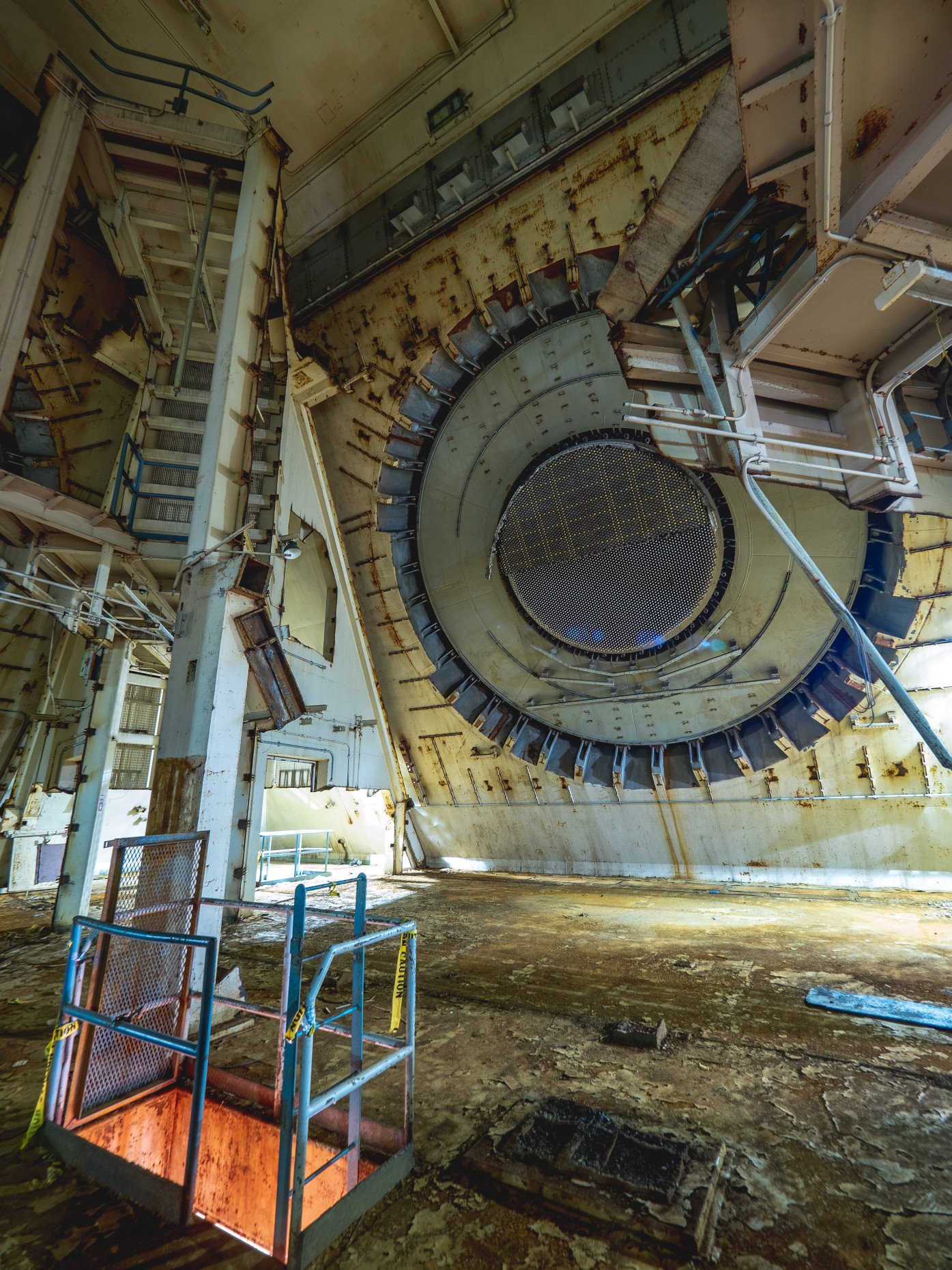
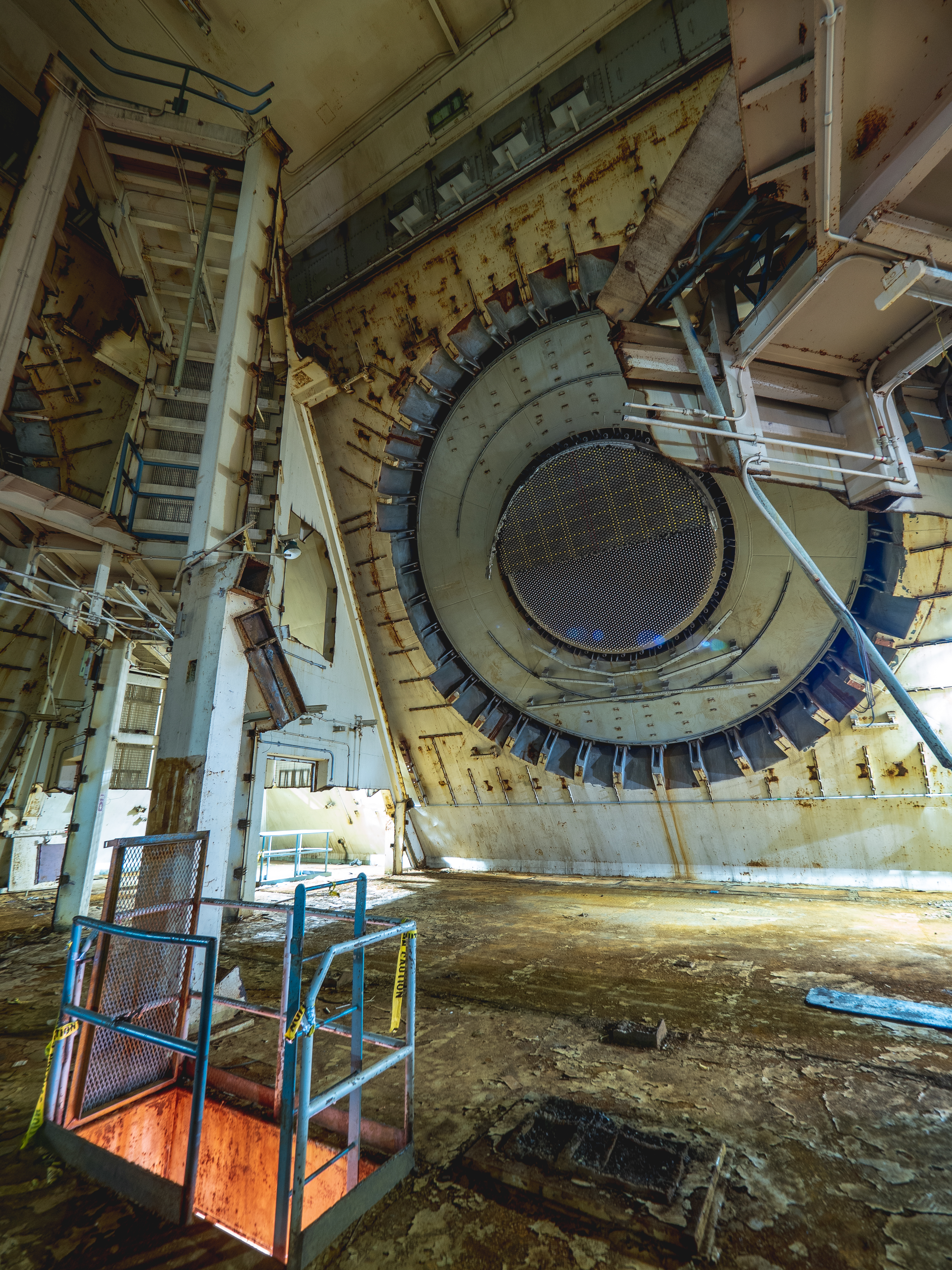
I022, I023: Level 4 room 405 (see diagram 1115 below).
- Waveguide penetrations into the anechoic chambers can be seen in their operational configuration.

- 1115: MSCB fourth floor layout.
More Level 4 (& 3) photos