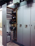
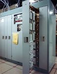
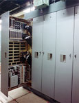
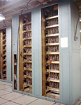
MSR / MSCB Photos: Interior
Receiver
- Photo Sources:
- 0nnn: Anonymous WECo engineer
-
1nnn: Ves Fulp -
8nnn: ABM Research and Development at Bell Labs -
Innn: Clint Esckilsen via Facebook (3)
- Photo Descriptions:
- John Roquet
-
Paul Tudor
Diagrams
- 8001: MSR Functional Block Diagram
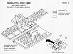
- 1116: Equipment layout, transmitter and receiver groups, rooms 229, 248.
-
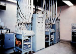
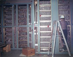
0031: One of the two RF receivers.
- The cryogenically cooled parametric amplifier is on the left side of the cabinet. Comments
- I021: RF receivers and parametric amplifiers. <$
-
0074:
- Taylor weighting filter used to collapse the chirped pulse modes (cabinet with all the knobs).
- Between the men in the picture appears to be the IF alignment test set.
-
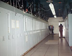
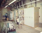
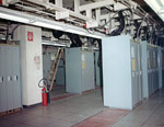
0077:
- Left foreground: radar return generator (RRG).
- Gap.
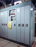
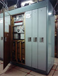
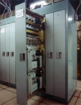
- Redundancy switching cabinets.
- Gap.
- Left background: IF receiver No. 1.
- Right background (near the personnel): Video receiver No. 1 and test trigger generator (TTG) No. 1.
-
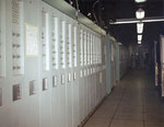
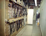
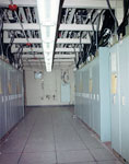
0078:
- Left: IF receiver.
- Right foreground: test trigger generator (TTG).
- Right background: video receiver.
-
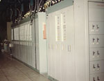
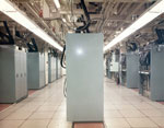
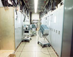
From foreground to background:
-
Receiver redundancy switches.
- Power distribution panel for this aisle.
- IF/Video receiver redundancy switch cabinets.
- Gap.
- Radar return generator (RRG).
-
Receiver redundancy switches.
PF & TG (Precision Frequency and Time Generator)
Unidentified

