Site Index, Search, Glossary. Updated 21 Apr 2006, flagged by <$
Home > System Components >
Remote Sprint Launch Sites > RSL Photo Galleries > RSL #3 Gallery A
RSL 3
Gallery A

(opens in a new window)
-
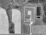
01733 :
USGS high altitude aerial photo of RSL 3 (1997).
-
(390 x 293 = 21k)
(800 x 600 = 92k)
-
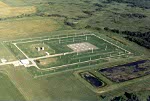
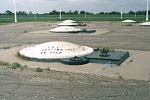
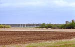
03905 :
Aerial photo of RSL 3 from the southeast (1996).
-
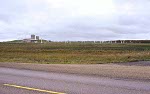
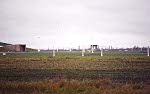
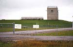
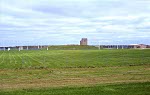
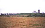
00709 :
RSL #3 from the southeast, photo taken from N.D. Highway 5 (1977).
-
The Sprint launch area is on the right.
-
(470 x 294 = 24k)
(918 x 575 = 80k)
-
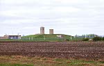
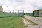
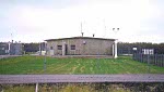
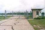
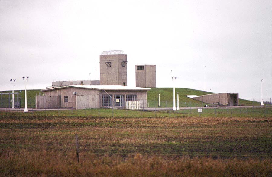
00309 :
Closer view of RSL #3 buildings from the southeast (1999).
-
Left to right:
-
Limited area sentry station (LASS).
-
Entrance to underground remote launch operations building (RLOB).
-
Exclusion area sentry station (EASS) (enforced two man rule for the
launch area).
-
(465 x 294 = 24k)
(907 x 573 = 79k)
-
00707 :
Left: entrance to the underground remote launch operations building (RLOB) (1977).
Right: Exclusion area sentry station (EASS) and south end of the Sprint launch area.
-
The white cap-like structures seen on the ground are Sprint launch cells.
-
00708 continues this photo to the north (right).
-
(470 x 295 = 21k)
(909 x 571 = 64k)
-
00708 :
North end of the Sprint launch area (1977).
-
Continuation of 00707 to the north (right).
-
(460 X 294 = 22k)
(918 x 586 = 64k)
-
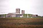
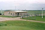
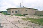
00706 :
View from the southeast (1977):
-
Foreground: limited area sentry station (LASS).
-
Background: remote launch operations building (RLOB).
-
(450 x 294 = 22k)
(900 x 588 = 64k)
-
00310 :
1999 version of photo 00706 (1999).
-
(455 x 295 = 24k)
(916 x 593 = 76k)
-
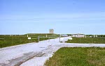
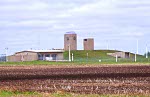
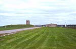
00806 :
Wide view of RSL #3 from the south at the turnoff from N.D. Highway 5 (1982).
-
(465 x 294 = 24k)
(919 x 582 = 75k)
-
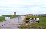
00702 :
Original RSL #3 sign (1977).
-
Apparently the RSL's were originally called RLS's.
-
(470 x 293 = 24k)
(918 x 572 = 63k)
-
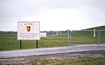
00314 :
Gate and current RSL #3 sign (1999).
-
(470 x 293 = 26k)
(919 x 573 = 80k)
-
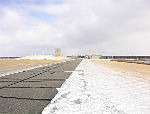
02613 :
RSL #3 from the south fence (winter) (2000).
-
00313 :
RSL #3 from the south fence (summer) (1999).
-
(460 x 294 = 19k)
(926 x 591 = 62k)
-
00703 :
Main gate and remote launch operations building (RLOB) (1977).
-
The cooling units in the center of the photo have since been removed.
-
(450 x 294 = 29k)
(904 x 590 = 98k)
-

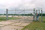
00705 :
Double gated sally port at the limited area sentry station (LASS) (1977).
-
(455 x 293 = 24k)
(911 x 587 = 77k)
-
02866 :
Closer view of the sally port at the limited area sentry station (2001).
-
02846 :
Limited area sentry station and sally port seen from the top of the remote launch operations
building (RLOB) (2001).
-
00701 :
Limited area sentry station (LASS) and sally port from the south (1977).
-
(515 x 293 = 24k)
(907 x 516 = 56k)
-
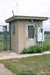
02853 :
Closer view of the limited area sentry station (LASS) (2001).
-
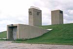
02865 :
Entrance tunnel to the remote launch operations building (RLOB) from the northeast (2001).
-
The generator exhaust ports are above left, air intake ports above right.
-
(442 x 295 = 19k)
(768 x 512 = 50k)
-
Photo by Ron Plante.
-
02868 :
Entrance tunnel to the remote launch operations building (RLOB) from the southeast (2001).
-
The security light, transformer, and electrical service box and meter
were not part of the original installation.
-
(436 x 295 = 22k)
(757 x 512 = 53k)
-
Photo by Ron Plante.
-
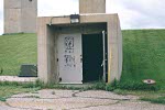
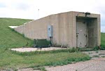
02862 :
Entrance to tunnel leading down to the remote launch operations building (RLOB) (2001).
-
Blast doors were present below at the boundary between the entrance tunnel and the RLOB structure.
-
The security light was not part of the original installation.
-
(442 x 295 = 24k)
(768 x 512 = 71k)
-
Photo by Ron Plante.
-
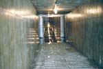
02861 :
Looking down the entrance tunnel to the main corridor in the remote launch operations building (RLOB) (2001).
-
Ceiling lights in the RLOB corridor are reflected in water on the floor.
-
(442 x 295 = 19k)
(768 x 512 = 42k)
-
Photo by Ron Plante.
-
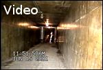
04203 :
<$ Video: Walking down the entrance tunnel to the main corridor in the remote launch operations building (RLOB) (2001).
-
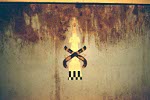
02860 :
Art work on the SOCC counter (2001).
-
02864 :
Sally port and exclusion area sentry station (EASS) that enforced the two man rule for the launch area (2001).
-
Only the brackets remain from the barbed wire barrier around the roof of the EASS.
-
(442 x 295 = 27k)
(768 x 512 = 81k)
-
Photo by Ron Plante.
-
02852 :
Closer view of the exclusion area sentry station (EASS) (2001).
-
02854 :
Entrance to the Sprint launch area (2001).
-
Just inside the entrance gate are Mark Berhow (left), co-author of
Rings of Supersonic Steel, and Jerry Greenwood (right),
SMDC resident engineer at the Mickelsen Complex.
-
(442 x 295 = 29k)
(768 x 512 = 83k)
-
Photo by Ron Plante.
-
02845 :
Sprint launch area (2001).
-
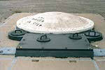
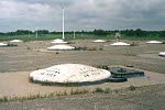
02850 :
Closeup of a Sprint launch station (2001).
-
The foundation of each of the 16 steel cylindrical Sprint launch stations was buried vertically
underground to a depth of some 32 ft and had an inner diameter of approximately 9.5 ft.
Each was closed with a hatch and had a launch preparation equipment chamber on a concrete base.
-
When operational, each cell contained a Sprint missile that would be launched by a gas-propelled
piston through its cell cover, which would be explosively fragmented to allow the missile's exit.
-
Launch area antennas (LAA's -- the vertical pipes next to each launch station at the MSR site)
were not used at the RSL's. Instead, pre-launch communication with RSL
missiles was accomplished via a data link system between the MSR and the RSL missile
control center (in the RLOB).
-
(442 x 295 = 24k)
(768 x 512 = 68k)
-
Photo by Ron Plante.
-

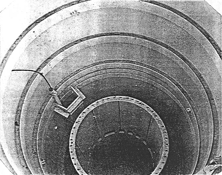
03012 :
View into Sprint silo.
-
02867 :
Another view of the Sprint launch area at RSL 3 (2001).
-
02855 :
Remote launch operations building (RLOB) from the launch area (2001).
-
00316 :
RSL #3 from the south, photo taken from N.D. Highway 5 (1999).
-
(465 x 294 = 24k)
(928 x 586 = 70k)
-
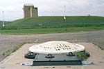
00318 :
RSL #3 from the southwest (1999).
-
Left: the white cap-like structures on the ground are Sprint launch cells.
-
Right: remote launch operations building (RLOB).
-
(465 x 295 = 28k)
(931 x 590 = 86k)
-
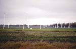
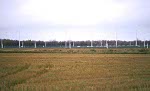
00634 :
RSL #3 from the southwest (1977).
-
Left: the white cap-like structures on the ground are Sprint launch cells.
-
Right: remote launch operations building (RLOB).
-
00635 continues this photo to the north (left).
-
(465 x 293 = 18k)
(915 x 577 = 64k)
-
00635 :
RSL #3 from the southwest (1977).
-
The white cap-like structures on the ground are Sprint launch cells.
-
Continuation of 00634 to the north (left).
-
(485 x 295 = 18k)
(899 x 546 = 57k)


