Site Index, Search, Glossary. Updated 22 Aug 2008, flagged by <$
Home > System Components > MSR Complex > MSR / MSCB >
MSR / MSCB Photo Galleries > External, Hi Altitude, Aerial, External Closeups (B: Nothumbs)
MSR / MSCB Photos: Exterior
High Altitude, Aerial, External Closeups, Gallery B (No Thumbs)
Gallery B
USGS high altitude photos; aerial photos; external closeup photos.
(Thumbnails)
-
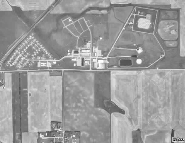
B01:
USGS high altitude aerial photo of the entire MSR site (1990).
-
The northern edge of the village of Nekoma is visible at the bottom of the photo.
-
(380 x 294 = 18k) Show | Omit descr (001706)
(611 x 472 = 25k) Show | Omit descr
-
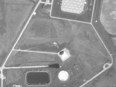
B02:
USGS high altitude aerial photo of the MSR (1990).
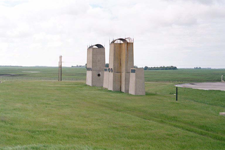
-
The Spartan missile field can be seen at the top of the photo.
-
(390 x 293 = 16k) Show | Omit descr (001721)
(800 x 600 = 32k) Show | Omit descr
-
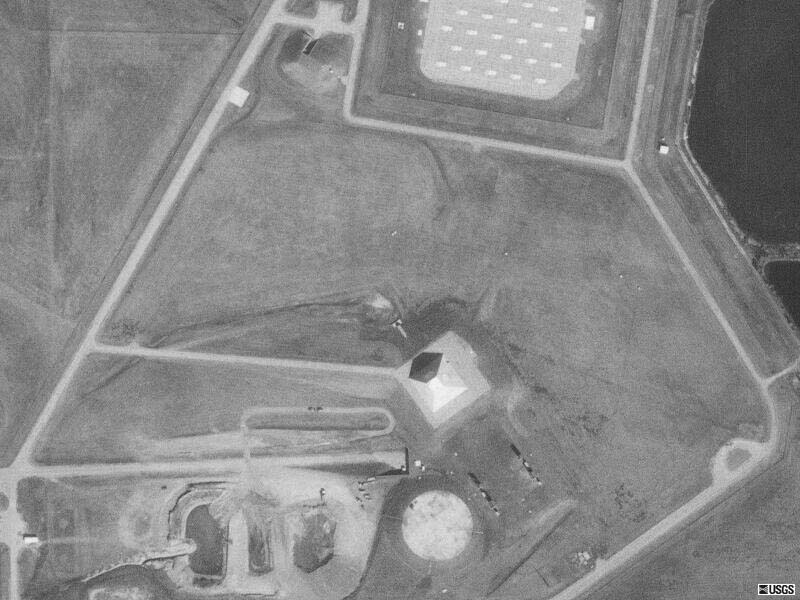
B03:
USGS high altitude aerial photo of the MSR (1997).
-
This 1997 version of B02 shows the reservoir drained and berms being removed. The water has been pumped out of the MSR/MSCB structure as part of an environmental cleanup to remove PCB contamination.
-
(390 x 293 = 17k) Show | Omit descr (001727)
(800 x 600 = 72k) Show | Omit descr
-
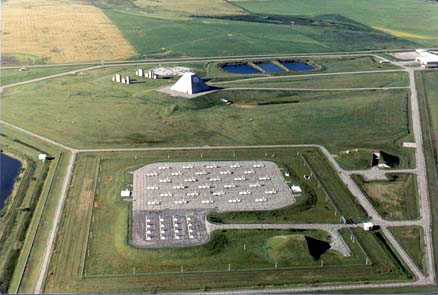
B04:
Aerial view from the north of the MSR tactical area (1996).
-
B05:
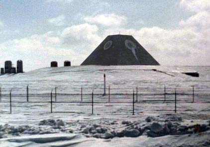
Winter view of the MSR from the northeast (1975).
-
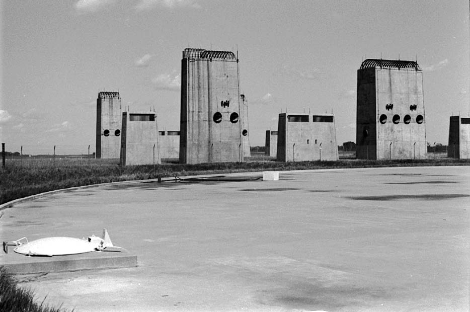
B06:
Access road to turret external areas (1982).
-
The tube like structure on the left is the emergency exit from the underground complex.
-
(470 x 293 = 25k) Show | Omit descr (000824)
(911 x 568 = 77k) Show | Omit descr
-
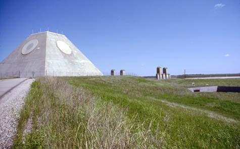
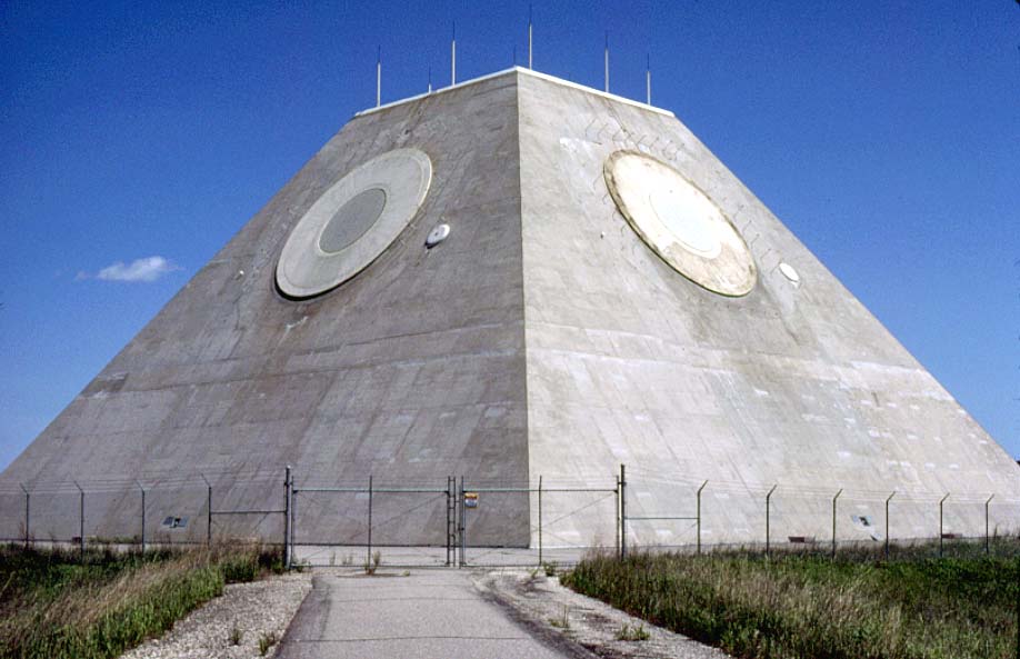
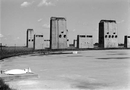
B07:
Farther along the access road to turret external areas (1982).
-
Entrance to underground complex can be seen on far right.
-
(475 x 295 = 24k) Show | Omit descr (000830)
(923 x 574 = 73k) Show | Omit descr
-
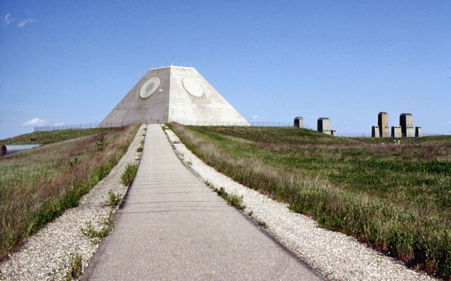
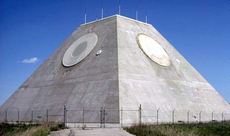
B08:
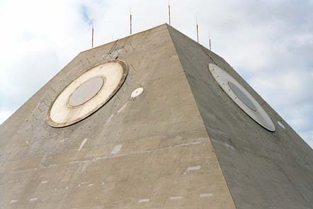
Closeup of the MSR showing northwest and southwest faces (1982).
-
(464 x 274 = 19k) Show | Omit descr (000825)
(918 x 593 = 71k) Show | Omit descr
-
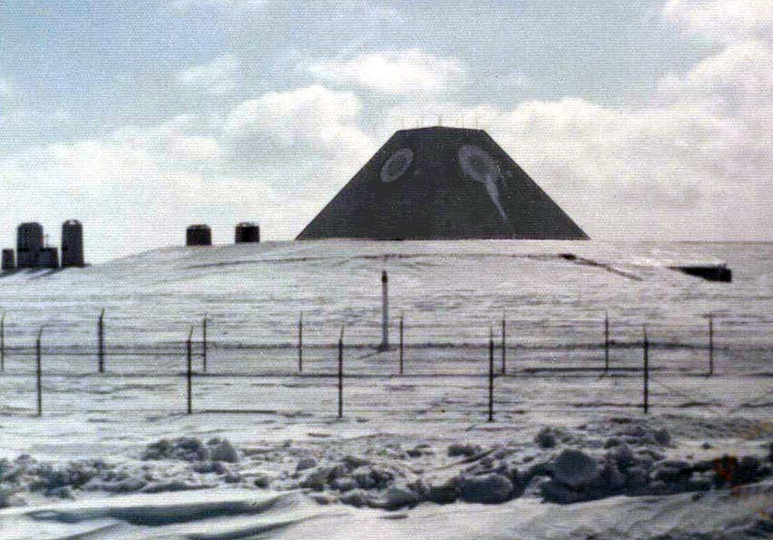
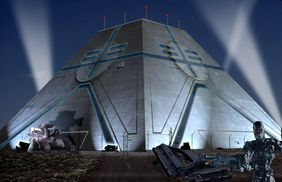
B09 :
<$ The MSR all dressed up as
Skynet from the Terminator franchise.
-
B10v:
Video: MSR turret (2001).
-
The roaring sound in the background is the wind.
-
mpg, 00:16
(170 x 120 = 896k)
(352 x 240 = 3.1m) 004201
-
Video by Ron Plante.
-
B11:
Aerial view of the MSR.
-
(464 x 324 = 27k) Show | Omit descr (001901)
-
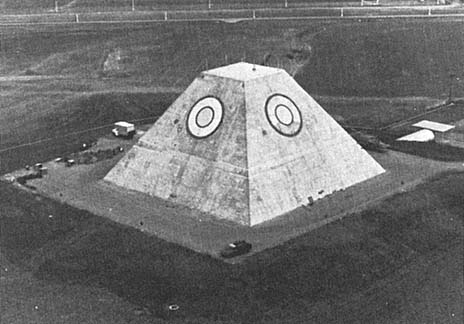
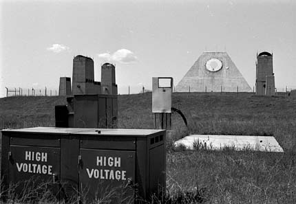
B12:
Closeup of the MSR, de-commissioning in progress (1977).
-
Uninstalled equipment can be seen laying around the base of the MSR pyramid.
-
(520 x 293 = 29k) Show | Omit descr (000619)
(902 x 509 = 63k) Show | Omit descr
-
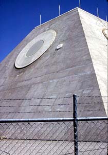
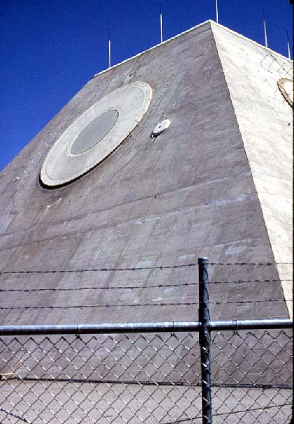
B13:
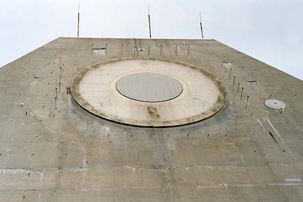
MSR northwest face (1982).
-
(210 x 303 = 18k) Show | Omit descr (000826)
(421 x 607 = 61k) Show | Omit descr
-
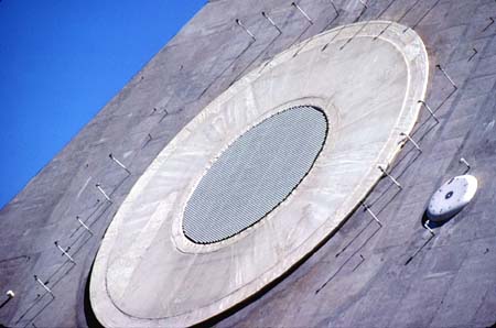
B14:
Antenna closeup, northwest face (1982).
-
Each of the four phased array antennas contained more than 5,000 array elements, was 13 feet in diameter, and weighed over 400,000 pounds.
-
The radar could continue to function even after the loss of some of the individual array elements.
-
The smaller antenna array located to the lower right of the main array was the Q-channel antenna. Its purpose was to reject or "blank" signals received on the array sidelobes (portions of the antenna response pattern not contained in the main beam).
-
The pipes and nozzles around the perimeter of the antennas were the antenna washdown devices. Their purpose was to wash and/or de-ice the antenna face/elements with a cleaning/de-icer solution.
-
The white plug-like device to the lower left of the main array was the exterior control for the antenna wash system.
-
Description from Clint Esckilsen and ABM R & D at Bell Labs.
-
(450 x 298 = 26k) Show | Omit descr (000828)
(919 x 609 = 84k) Show | Omit descr
-
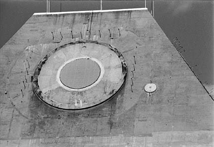
B15:
Anetnna closeup, southwest face (1982).
-
(430 x 295 = 021k) Show | Omit descr (000926)
(945 x 616 = 101k) Show | Omit descr
-
B16:
Northeast (left) and northwest (right) antenna faces (2001).
-
Five lightening arrestors can be seen above the turret.
-
(442 x 295 = 17k) Show | Omit descr (002810)
(768 x 512 = 46k) Show | Omit descr
-
Photo by Ron Plante.
-
B17:
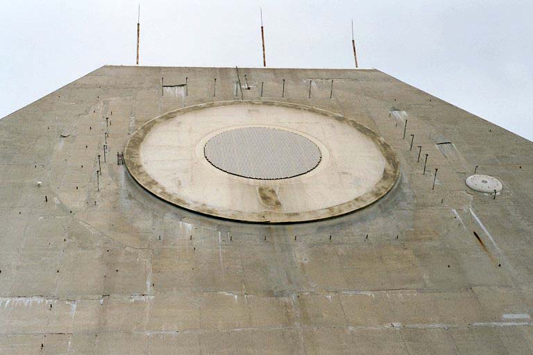
Northeast antenna face (2001).
-
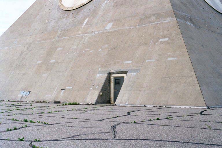
B18:
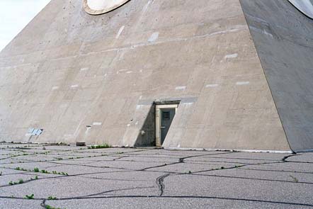
Northeast turret wall (2001).
-
The door provided an emergency escape route from the third level of the MSCB.
-
(442 x 295 = 25k) Show | Omit descr (002807)
(768 x 512 = 73k) Show | Omit descr
-
Photo by Ron Plante.
-
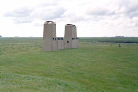
B19:
Intake / exhaust stacks on the east side of the power plant (2001).
-
The taller structures were exhaust stacks, the lower were for air intake.
-
These stacks were for prime mover modules 1, 3, and 5.
-
(442 x 295 = 15k) Show | Omit descr (002822)
(768 x 512 = 45k) Show | Omit descr
-
Photo by Ron Plante.
-
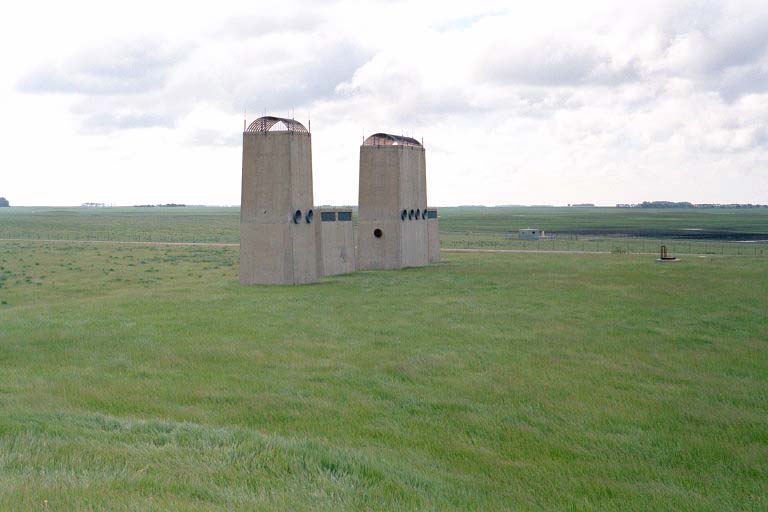
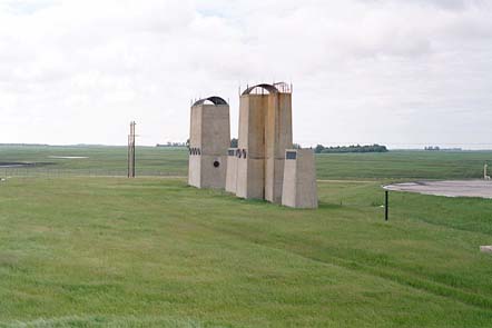
B20:
Intake / exhaust stacks on the west side of the power plant (2001).
-
The taller structures were exhaust stacks, the lower were for air intake.
-
These stacks were for prime mover modules 2, 4, and 6.
-
The heat sink is visible at the right of the photo.
-
(442 x 295 = 16k) Show | Omit descr (002819)
(768 x 512 = 44k) Show | Omit descr
-
Photo by Ron Plante.
-
B21:
MSR heat sink (1982).
-
The heat sink's function was to provide cooling for MSR components while the complex was "buttoned up" during a nuclear attack.
-
(430 x 297 = 14k) Show | Omit descr (000925)
(934 x 620 = 61k) Show | Omit descr
-
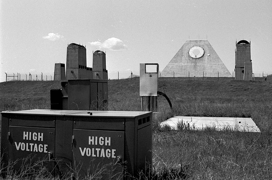
B22:
Transformers at commercial power substation (1982).
-
(430 x 297 = 19k) Show | Omit descr (000908)
(933 x 619 = 87k) Show | Omit descr
-
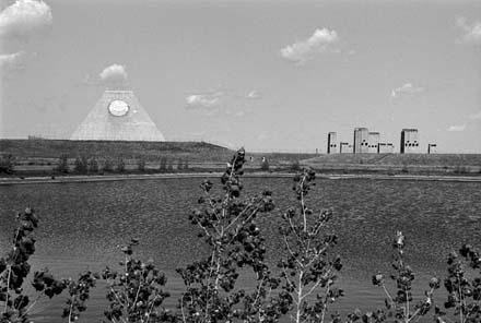
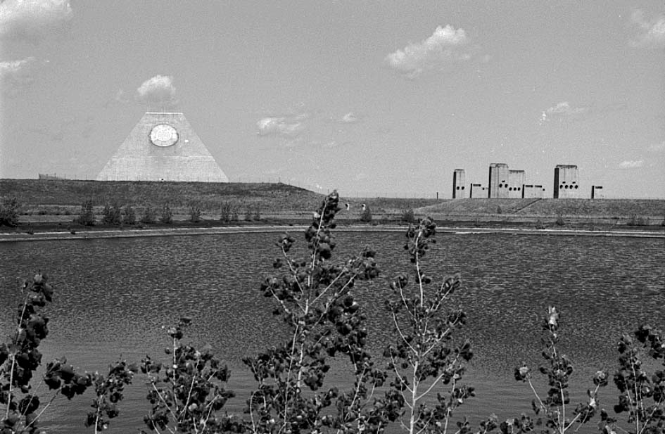
B23:
Water storage reservoir (1982).
-
Water from the reservoir leaked into the MSR structure after the site was de-activated.
-
The reservoir was later drained and the berms removed as part of de-watering of the MSCB and its power plant during an environment cleanup.
-
(440 x 296 = 22k) Show | Omit descr (000915)
(945 x 617 = 98k) Show | Omit descr