Site Index, Search, Glossary. Updated 22 Aug 2008, flagged by <$
Home > System Components > MSR Complex > MSR Missile Support Areas >
Photo Galleries > Gallery 1 (No Thumbnails)
MSR Missile Support Gallery 1 (No Thumbnails)
(Thumbnails)
-
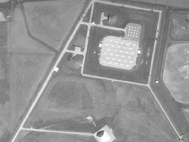
001:
USGS high altitude aerial photo of the MSR missile support areas (1990).
-
The smaller square Sprint field (16 missiles) is above, with the larger Spartan field (30 missiles) below.
-
The MSR pyramid is visible at the bottom of the photo.
-
(390 x 293 = 16k) Show | Omit descr (001710)
(800 x 600 = 31k) Show | Omit descr
-
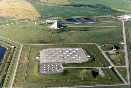
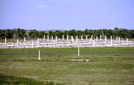
002:
Aerial view from the north of the MSR tactical area (1996).
-
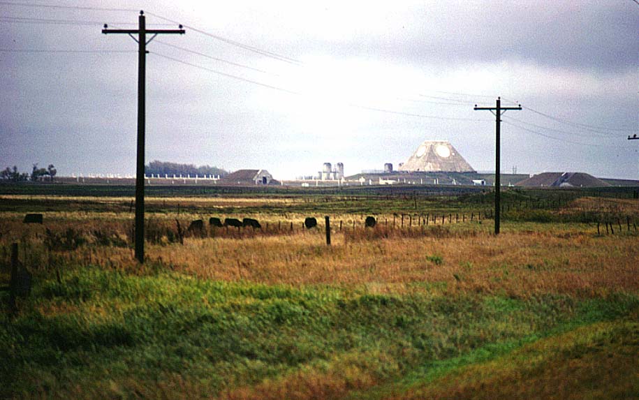
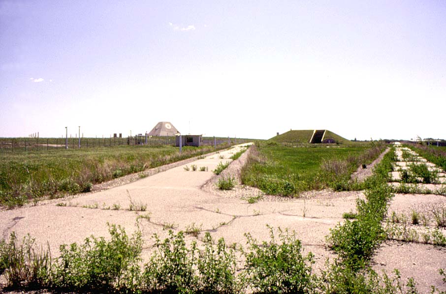
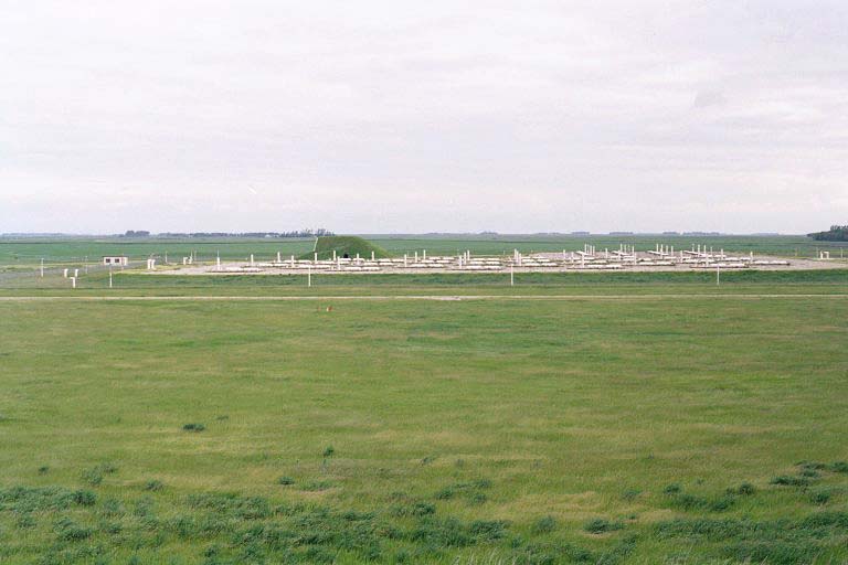
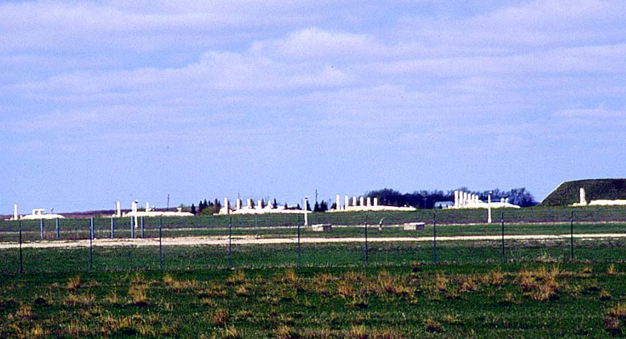
003:
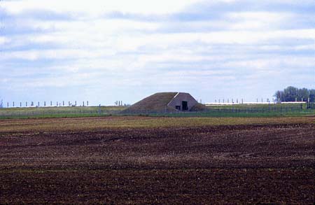
Missile support areas from the northwest, taken from N.D. Highway 1 (1977).
-
Left to right:
launch area , warhead building, MSR pyramid, universal missile building.
-
(470 x 294 = 25k) Show | Omit descr (000633)
(915 x 573 = 83k) Show | Omit descr
-
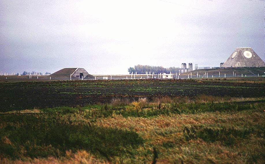
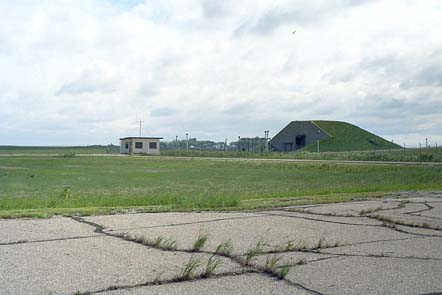
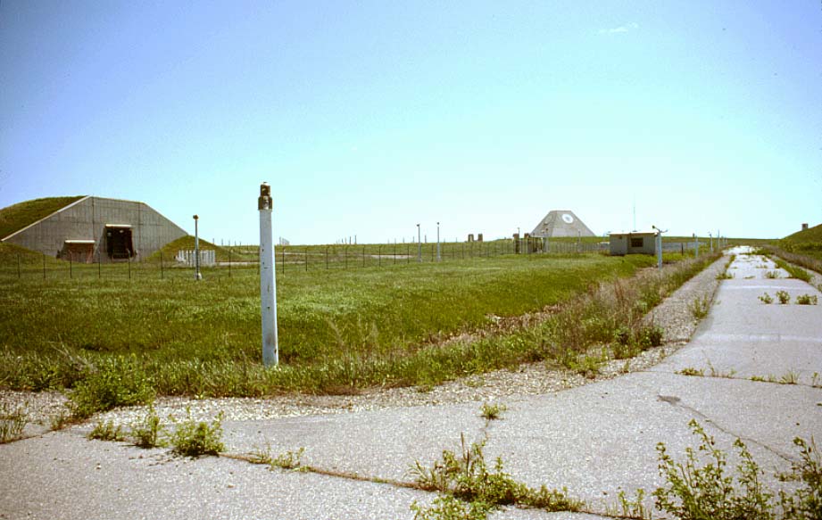
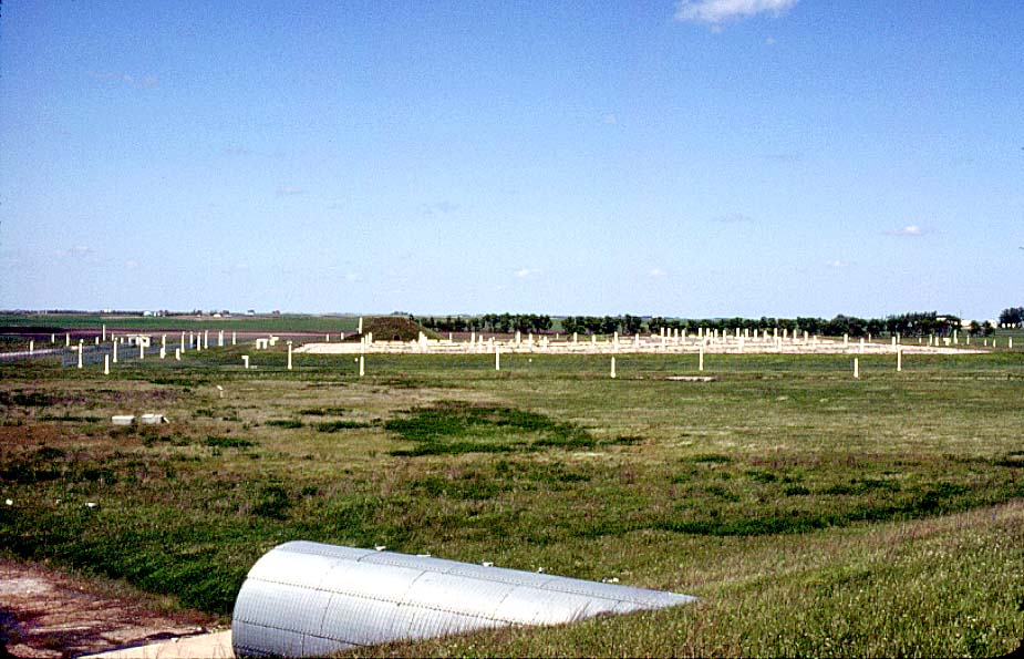
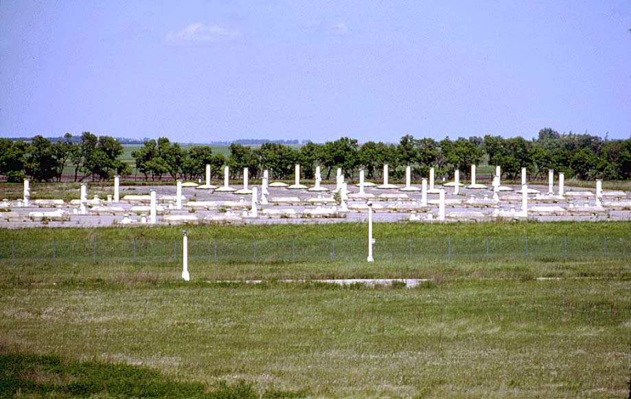
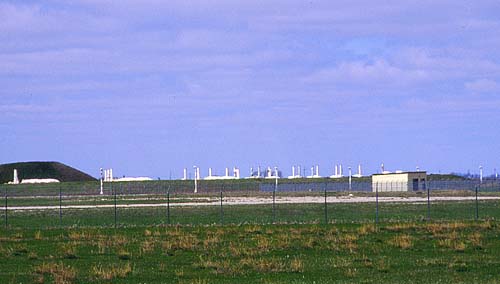
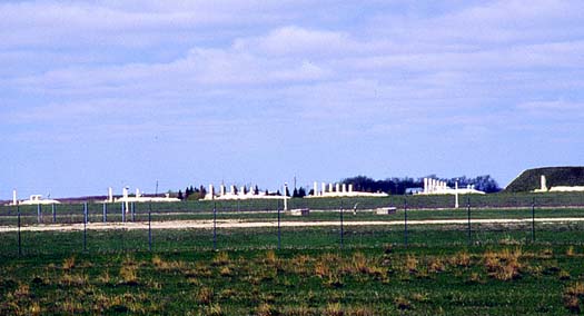
004:
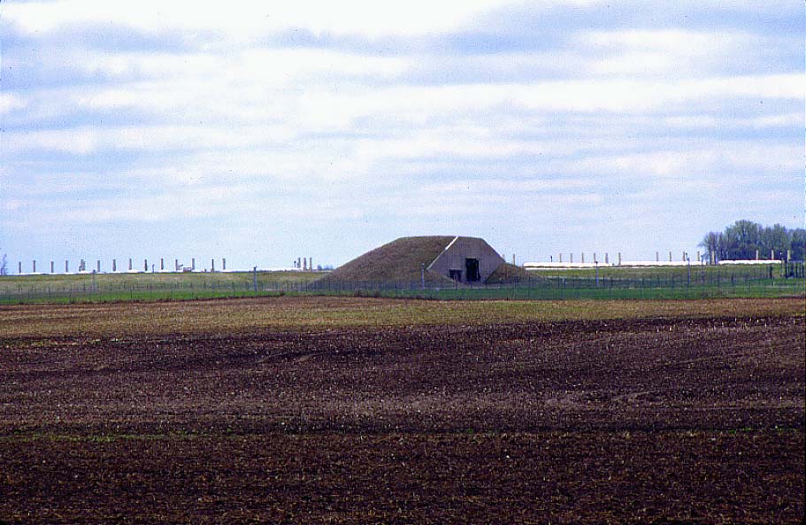
Closer view of missile support areas from the northwest (1977).
-
Exclusion area sentry station (EASS) is the small building to the right of center.
-
Vertical white poles in the foreground are the light standards that lined all roads in the complex but have since been removed.
-
Vertical white poles in the background were used to communicate with the missiles via the radar prior to missile launch. (See photo 031 for details.)
-
(470 x 290 = 23k) Show | Omit descr (000632)
(918 x 567 = 81k) Show | Omit descr
-
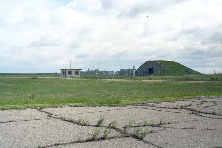
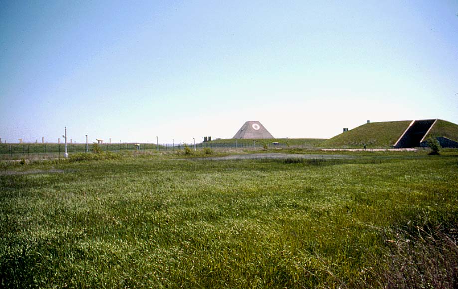
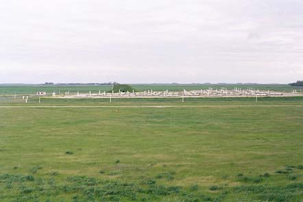
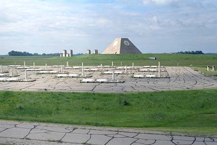
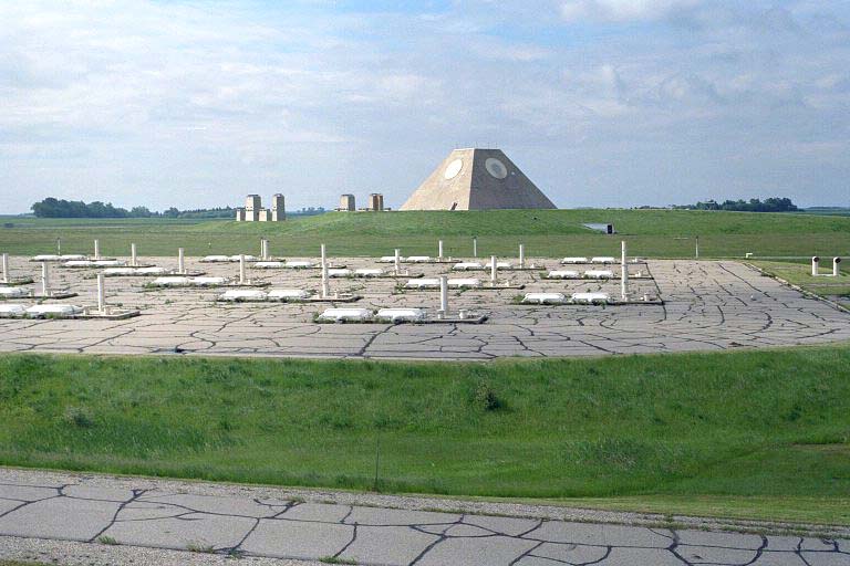
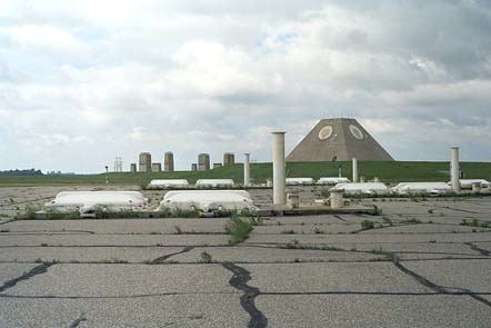
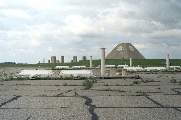
005:
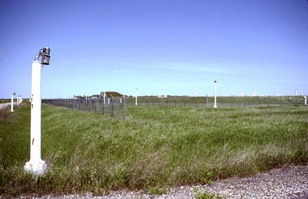
Later photo of launch area and warhead building from the northwest (1999).
-
Sprint launchers are in left background; Spartan launchers are in right background.
-
All the light standards have been removed. The vertical poles were used to communicate with the missiles via the radar prior to missile launch. (See photo 031 for details.)
-
(450 x 293 = 023k) Show | Omit descr (000401)
(911 x 593 = 100k) Show | Omit descr
-
006:
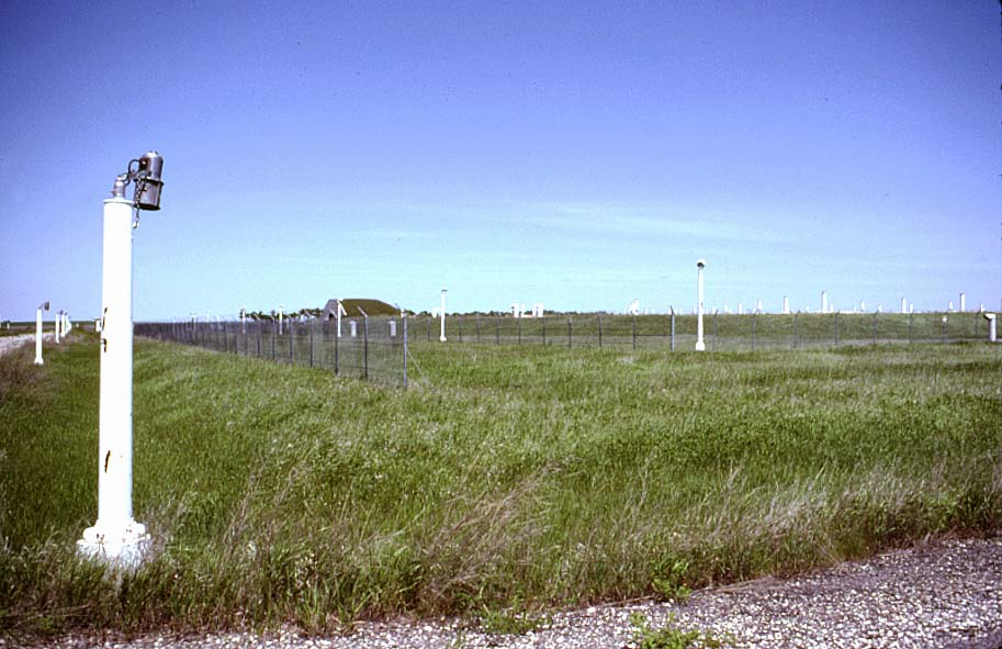
View toward the warhead building from the universal missile building (1982).
-
Closeup of the light standards that lined all roads in the complex but have since been removed.
-
(450 x 291 = 27k) Show | Omit descr (000817)
(913 x 591 = 94k) Show | Omit descr
-
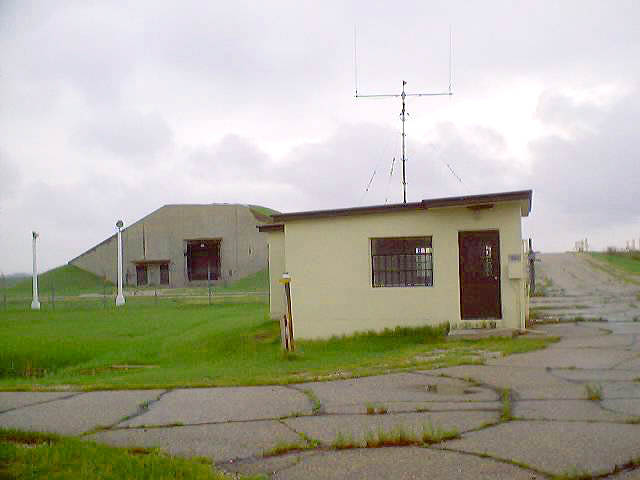
007:
Exclusion area sentry station (left) and warhead handling building (right) seen from the universal missile building (2001).
-
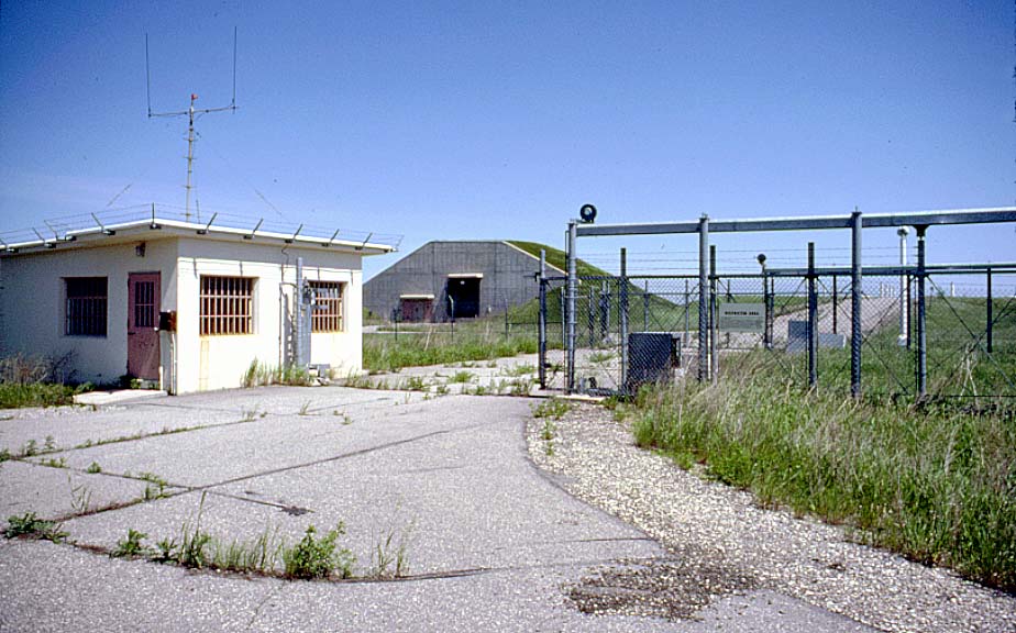
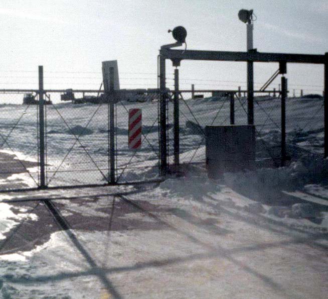
008:
Exclusion area sentry station (EASS) (1982).
-
The double gated sally port enforced the two man rule for the exclusion area (warhead building and launch area).
-
Warhead building is in the center background.
-
North end of the Sprint launch area can be seen in right background at end of the road.
-
(470 x 293 = 037k) Show | Omit descr (000818)
(924 x 576 = 109k) Show | Omit descr
-
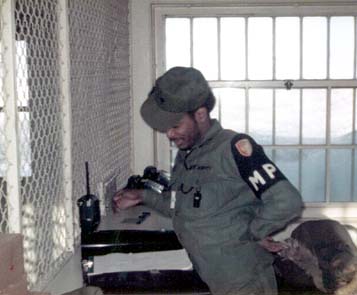
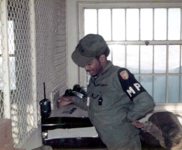
009:
MP Eric Johns in the EASS (1975).
-
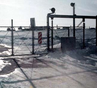
010:
Closer winter view of the EASS sally port (1975).
-
The Sprint launch area is visible in the background.
-
(324 x 295 = 21k) Show | Omit descr (004036)
(654 x 595 = 64k) Show | Omit descr
-
Photo by John Thompson.
-
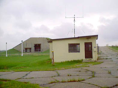
011:
EASS from the west, warhead building in the background (2003).
-
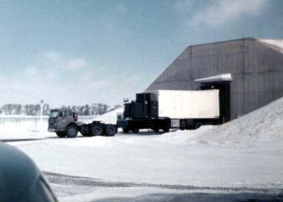
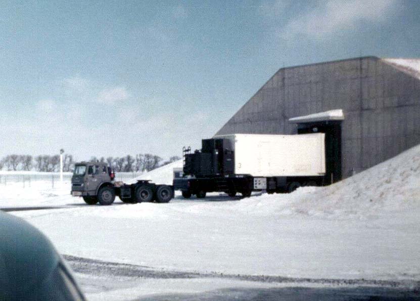
012:
Warhead handling building with Sprint transport vehicle at loading dock (1975).
-
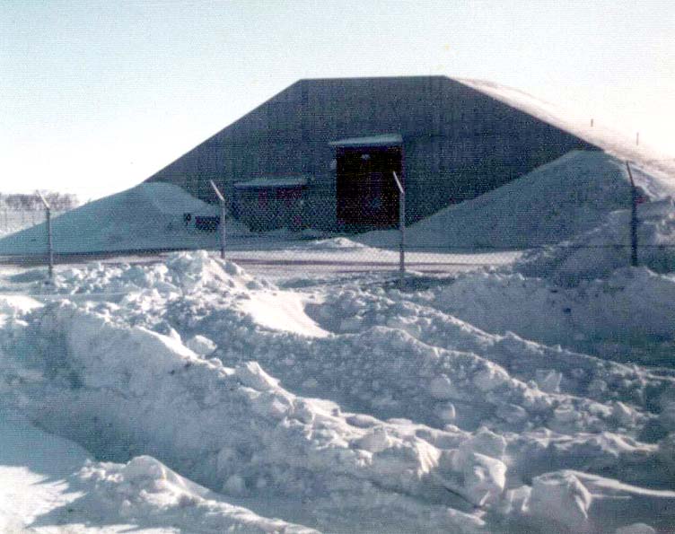
013:
Warhead handling building, winter photo (1975).
-
014:
Warhead handling building (2001).
-
015:
View towards the MSR pyramid from the northwest (1982).
-
Warhead building is on the left, exclusion area sentry station (EASS) is just to the right of the MSR pyramid.
-
(460 x 291 = 25k) Show | Omit descr (000820)
(921 x 583 = 86k) Show | Omit descr
-
016:
View towards the MSR pyramid from the northwest (1982).
-
Exclusion area sentry station (EASS) is just to the right of the MSR pyramid. The universal missile building is just to the right of center.
-
(440 x 290 = 028k) Show | Omit descr (000821)
(906 x 598 = 100k) Show | Omit descr
-
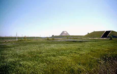
017:
View towards the MSR pyramid from the northwest (1982).
-
Universal missile building is on the right.
-
(460 x 290 = 27k) Show | Omit descr (000819)
(919 x 579 = 98k) Show | Omit descr
-
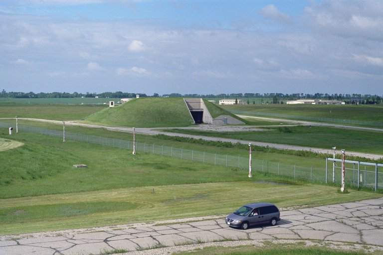
018:
Universal missile building from the top of the warhead handling building (2001).
-
The admin building is in the background just to the right of the universal missile building.
-
(442 x 295 = 22k) Show | Omit descr (002882)
(768 x 512 = 74k) Show | Omit descr
-
Photo by Ron Plante.
-
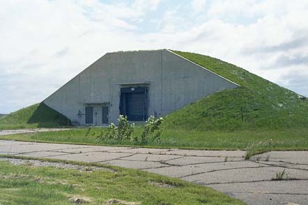
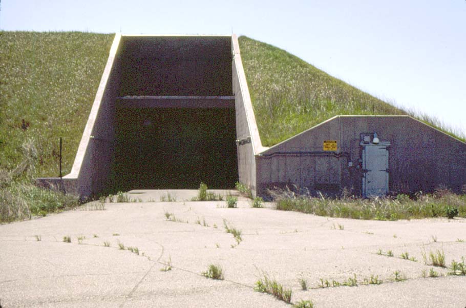
019:
Universal missile building (1982).
-
The dark tunnel like area leads to the loading dock and entrance door.
-
The bunker like structure on the right (with door) was the explosives service magazine.
-
(440 x 291 = 21k) Show | Omit descr (000812)
(910 x 601 = 77k) Show | Omit descr
-
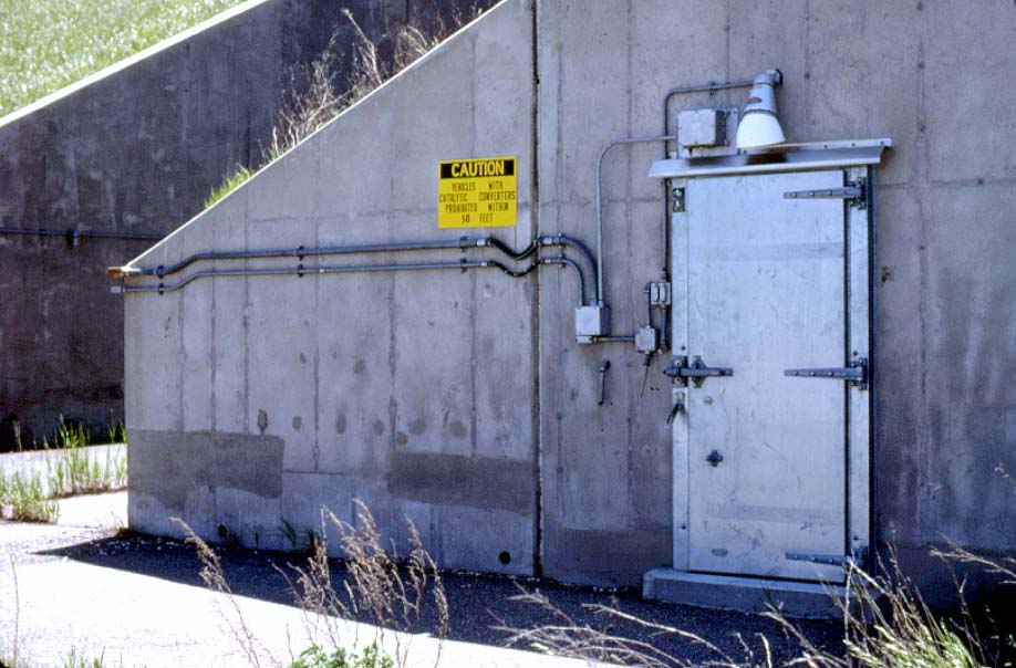
020:
Entrance to the explosives service magazine, universal missile building (1982).
-
The flexible conduit connectors at the building joint (just below the "Caution" sign) illustrate the efforts taken to deal with building motion that would occur under nuclear attack conditions.
-
Catalytic converters were prohibited within 50 feet since they can reach extremely high temperatures. If a motor isn't kept tuned up and is misfiring or dumping excess fuel, the converter can glow red hot from the chemical reaction and can start fires in tall weeds or grass, even with the heat shield installed.
-
(456 x 300 = 27k) Show | Omit descr (000816)
(918 x 604 = 81k) Show | Omit descr
-
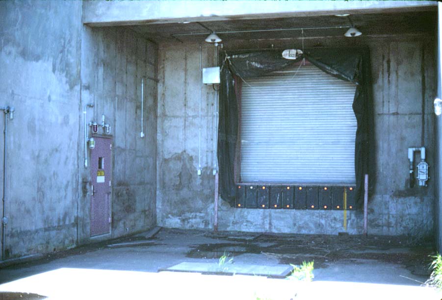
021:
Universal missile building loading dock (1982).
-
Entrance to the universal missile building was through the door on the left.
-
(425 x 289 = 22k) Show | Omit descr (000815)
(901 x 612 = 71k) Show | Omit descr
-
022:
Launch area from the universal missile building (1982).
-
Spartan launchers are on the right, Sprint launchers are in the left background.
-
The vertical white poles near each launcher were used to communicate with the missiles via the radar prior to missile launch. (See photo 031 for details.)
-
(460 x 292 = 27k) Show | Omit descr (000814)
(916 x 581 = 86k) Show | Omit descr
-
023:
Back side of the universal missile building from the MSR (left) (2001).
-
The exclusion area sentry station, launch area, and warhead building are on the right.
-
(442 x 295 = 17k) Show | Omit descr (002803)
(768 x 512 = 46k) Show | Omit descr
-
Photo by Ron Plante.
-
024:
Launch area from the MSR (1982).
-
Exclusion area sentry station (EASS) can be seen on the left.
-
Warhead handling building is just left of center.
-
The tube like structure at the bottom is the emergency exit from level 2 of the MSR underground complex.
-
(455 x 293 = 032k) Show | Omit descr (000827)
(925 x 595 = 113k) Show | Omit descr
-
025:
Launch area from the MSR (2001).
-
026:
Closer view of the launch area from the MSR (1982).
-
Spartan launchers are in the foreground, Sprint launchers are in the background.
-
(460 x 291 = 31k) Show | Omit descr (000829)
(919 x 582 = 92k) Show | Omit descr
-
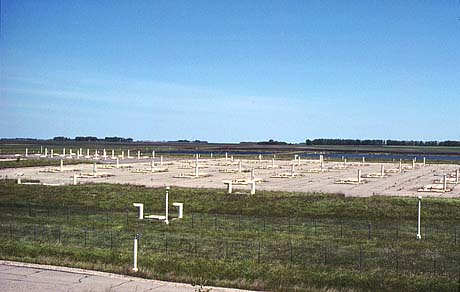
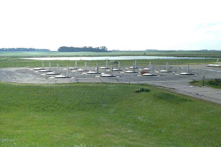
027:
Sprint launch area from the warhead handling building (2001).
-
028:
Sprint launch area from the southeast (1999).
-
(500 x 284 = 22k) Show | Omit descr (000420)
(903 x 513 = 71k) Show | Omit descr
-
029:
Sprint launch area (2001).
-
030:
Unidentified MP at a Sprint silo (1975).
-
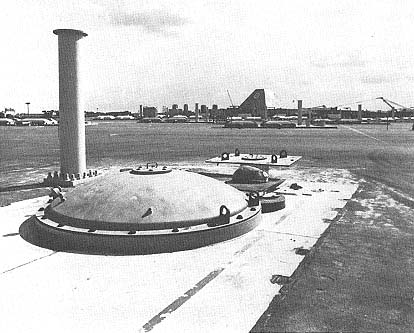
031:
Exterior of a Sprint launch cell.
-
The vertical white pole to the left of the launch cell was the launch area antenna (LAA). It was used by the radar to communicate with the missile in its underground silo prior to missile launch. (Also used for Spartan.)
-
Each LAA consisted of a reradiating horn mounted in an 18 inch diameter steel pipe. The pipe and its internal conduit had a weatherproofed cover.
-
LAA's were not used at the RSL's. Instead, pre-launch communication with RSL missiles was accomplished via a data link system between the MSR and the RSL missile control center (in the RLOB).
-
Following launch, the radar established its normal communication link directly with the missile, whether launched from the MSR complex or an RSL.
-
The launch cell cover in this photo is a temporary version used during construction. These were replaced with "explodable" covers before tactical operations began.
-
(414 x 333 = 33k) Show | Omit descr (001907)
-
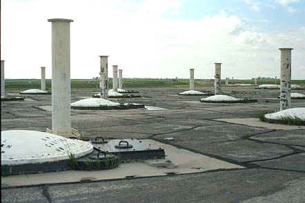
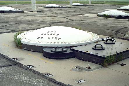
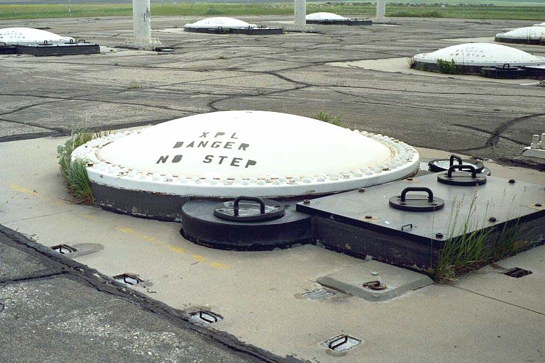
032:
Sprint launch station closeup (2001).
-
The foundation of each of the 16 steel cylindrical Sprint launch stations was buried vertically underground to a depth of some 32 ft and had an inner diameter of approximately 9.5 ft. Each was closed with a hatch and had a launch preparation equipment chamber and a launch area antenna (see 031) on a concrete base.
-
When operational, each cell contained a Sprint missile that would be launched by a gas-propelled piston through its cell cover, which would be explosively fragmented to allow the missile's exit.
-
(442 x 295 = 30k) Show | Omit descr (002881)
(768 x 512 = 87k) Show | Omit descr
-
Photo by Ron Plante.
-
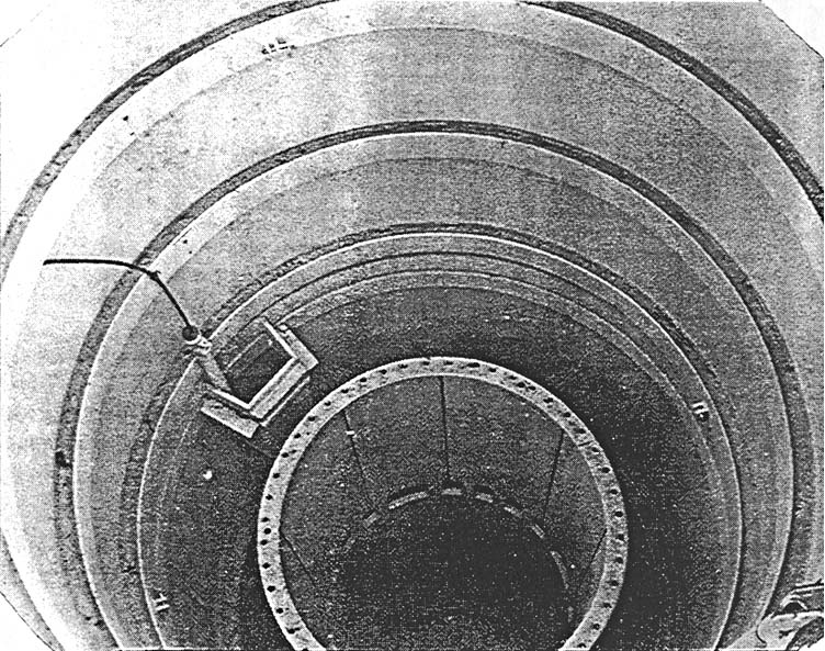
033:
View into Sprint silo.
-
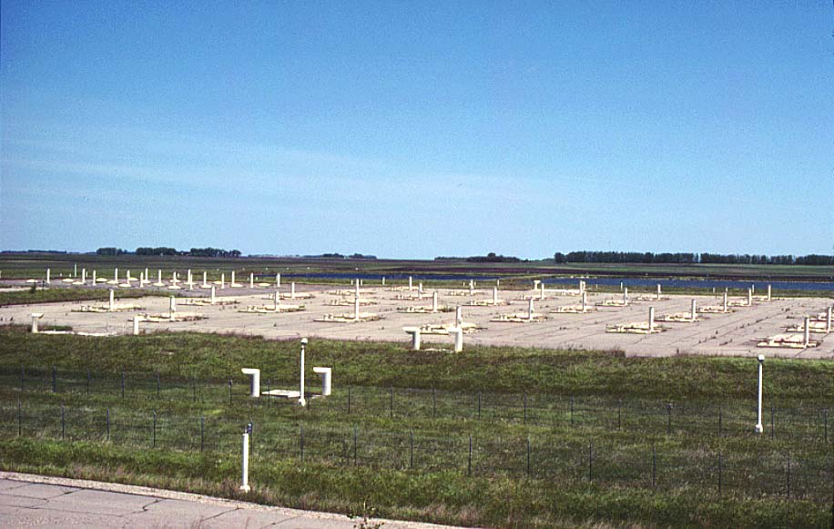
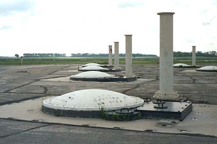
034:
Another view of the Sprint launch area showing the launch area antennas (see 031) (2001).
-
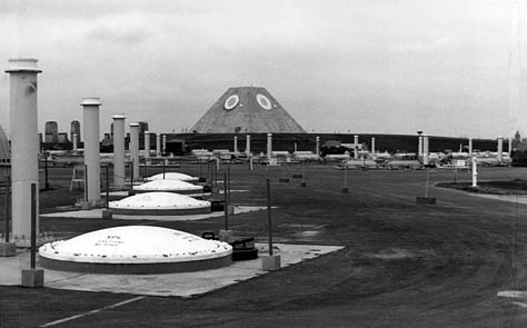
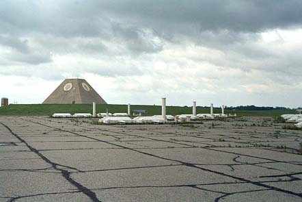
035 :
<$ Sprint launch area on the left, Spartan launch area on the right, MSR in the background.
-
(0474 x 295 = 039k) Show | Omit descr (002961)
(1059 x 659 = 124k) Show | Omit descr
-
Source: Seize the High Ground.
-
036:
Spartan launch area from the warhead building (2001).
-
037:
Spartan launch area from the southeast (1999).
-
(525 x 284 = 28k) Show | Omit descr (000419)
(914 x 495 = 99k) Show | Omit descr
-
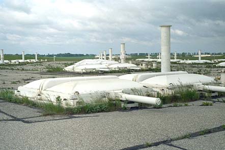
038:
Spartan launch area (photo 1) (2001).
-
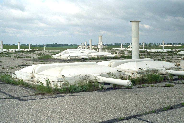
039:
Spartan launch area (photo 2) (2001).
-
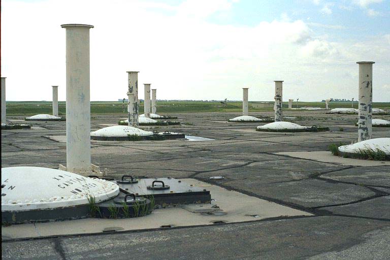
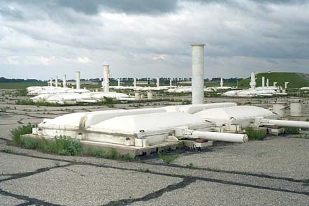
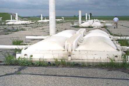
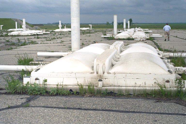
040:
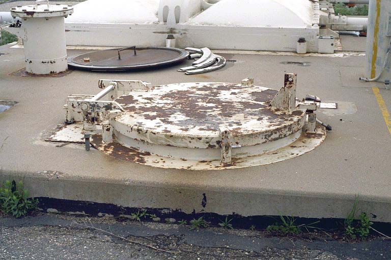
Spartan launch station closeup (2001).
-
The Spartan launch station was a reinforced, rectangular concrete structure inside a missile cell (silo), 9 by 9 by 72 ft, sloping downward 5 degrees from the vertical.
-
Each of the 30 Spartan launch stations had a storage chamber for the missile, an exhaust duct for gas removal during firing, and a launch preparation and equipment vault above a mechanical and electrical equipment vault (both 11.5 by 9 ft underground and used for installation/maintenance).
-
The launch station cover would automatically open in tactical situations.
-
Each launch station had a launch area antenna (LAA) similar to Sprint's (see 031).
-
The silos had a center-to-center separation distance of 73 ft and were laid out in parallel rows. The launch station, itself, extended approximately 6 inches above ground level.
-
(442 x 295 = 32k) Show | Omit descr (002876)
(768 x 512 = 98k) Show | Omit descr
-
Photo by Ron Plante.
-
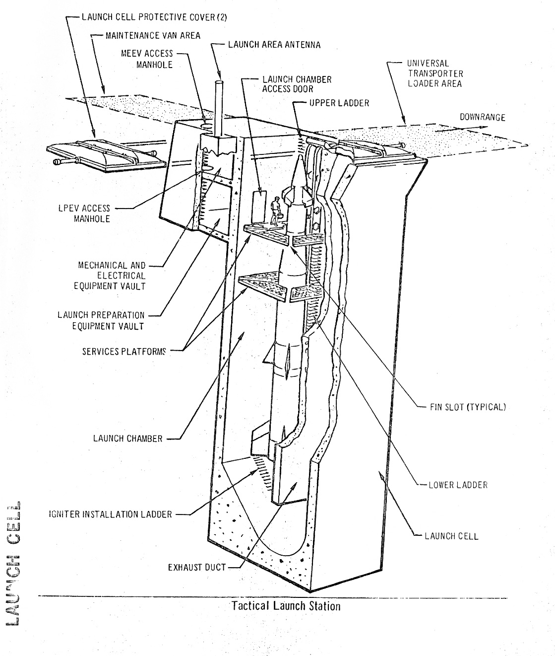
041:
Spartan engineering diagram "Tactical Launch Station (Launch Cell)".
-
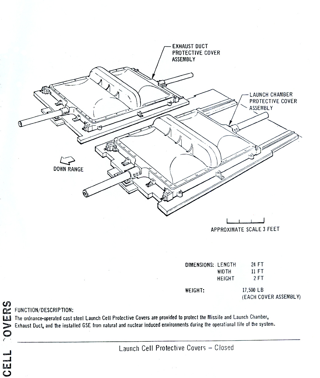
042:
Spartan engineering diagram "Launch Cell Protective Covers - Closed (Cell Covers)"
-
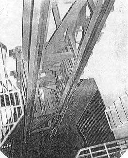
043:
View within Spartan missile silo.
-
Launch rail is located in the north section of all silos.
-
At right is the Mechanical Electrical Equipment Vault (MEEV).
-
Top of photo is "up", bottom is "down".
-
(264 x 325 = 025k) Show | Omit descr (HAER ND-9-F-6 003011)
(592 x 730 = 136k) Show | Omit descr
-
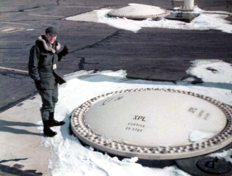
044:
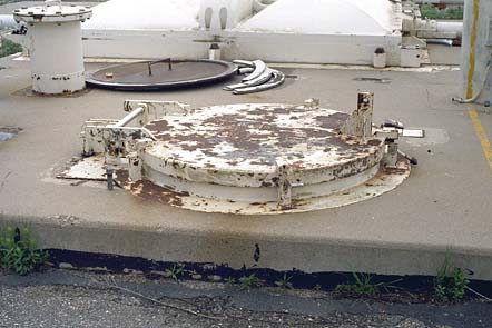
Spartan launch station access hatch (2001).
-
Provided access to the launch preparation and equipment vault above a mechanical and electrical equipment vault (both 11.5 by 9 ft and used for installation/maintenance).
-
(442 x 295 = 31k) Show | Omit descr (002875)
(768 x 512 = 93k) Show | Omit descr
-
Photo by Ron Plante.
-
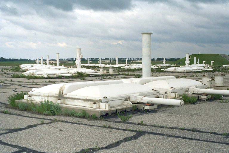
045:
Spartan launch area (photo 3) (2001).
-
The universal missile building is in the distance on the left.
-
(442 x 295 = 27k) Show | Omit descr (002873)
(768 x 512 = 76k) Show | Omit descr
-
Photo by Ron Plante.
-
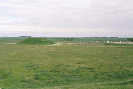
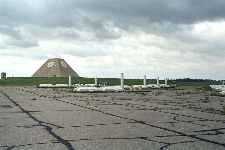
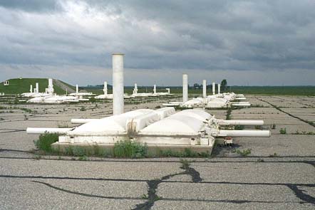
046:
Spartan launch area, MSR in the background (2001).
-
047:
Spartan launch area (photo 4) (2001).